Working conditions
Identify temperature, contact fluids and repeated movement.

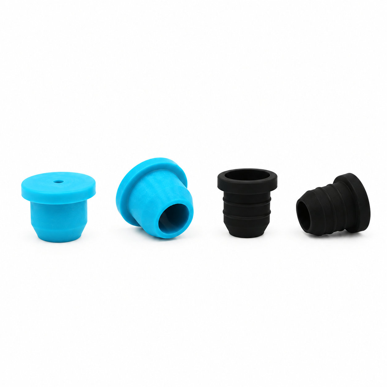
Custom manufacturing example · Custom solid food grade silicone rubber stopper for test tube
CUSTOM RUBBER & SILICONE MANUFACTURING
A custom component for your assembly.
Define the mating surfaces, dimensions and working conditions. ETOL manufactures the part to the agreed design and material.
Share the part, its application and your estimated quantity.

Selected for the contact, temperature and movement
Define the visible surfaces and intended color
Develop holes, lips and walls around the mating parts
Match the attachment and installation method
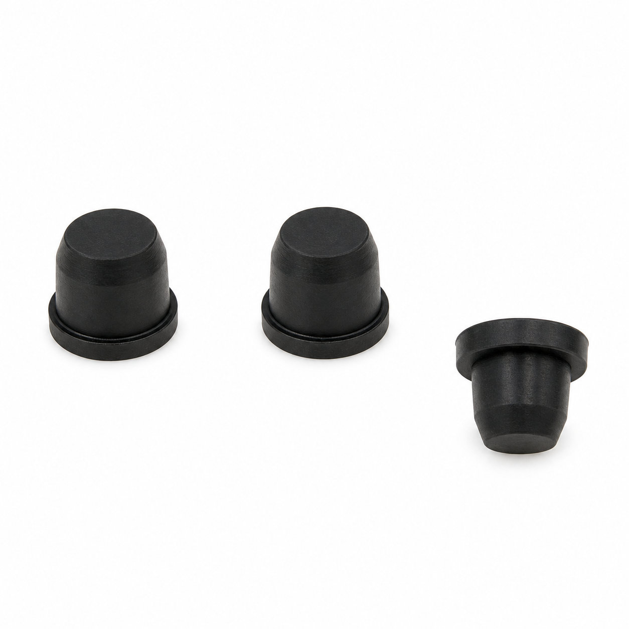
A silicone rubber stopper for test tube applications can be custom developed as a solid closure. Its body should suit the tube's internal profile and mouth, with an exterior that supports controlled insertion and removal. The finished silicone formulation should be selected for the actual contents and cleaning or processing conditions.
Check the tube rim and the intended insertion depth together. The stopper should establish its seat without excessive force against the tube or unnecessary extension into the contents. A solid body provides no through passage, so the complete procedure should suit a closed opening of this type.
Keep the inserted surface free of contamination during handling. Inspect the tube and rubber for damage before fitting, especially if closures are removed and replaced during preparation. Avoid puncturing or modifying the body to accommodate an unplanned access method. Food related material selection and laboratory suitability each depend on the intended conditions; neither should be inferred from appearance. Separate similar stoppers by their working dimensions to preserve the correct tube pairing.
Photos illustrate structure or material appearance only. The stopper should establish its seat without excessive force against the tube or unnecessary extension into the contents. ETOL directly manufactures custom-shaped silicone and rubber parts to your requirements.
FIND THE RIGHT FIT
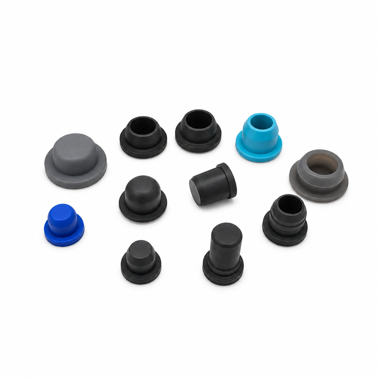
Choose a blind-hole, tapered, undercut or solid T-shaped profile, then compare its dimensions with the opening and available seating depth. Each profile has its own drawing and dimension meanings.
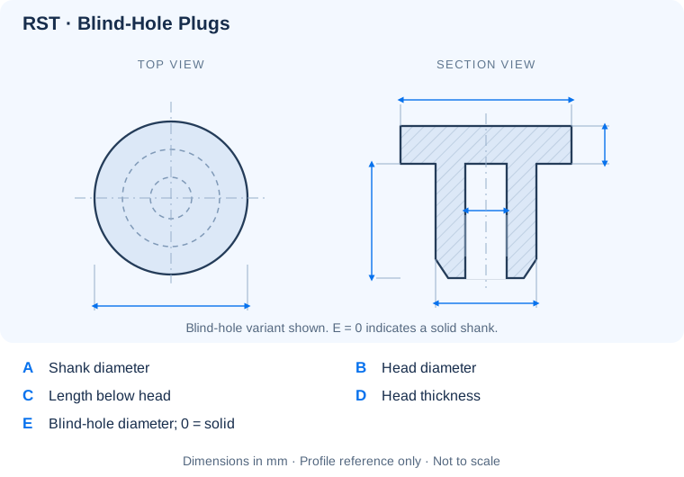
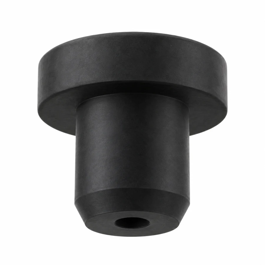
155 T-shaped plug sizes. Match shank diameter A, head diameter B, shank length C and head thickness D. E is the bottom blind-hole diameter; E = 0 indicates a solid shank.
| P/N | A | B | C | D | E | Unit |
|---|---|---|---|---|---|---|
| RST2.5-5.5-5.3 | 2.5 | 5.5 | 5.3 | 2 | 0 | mm |
| RST2.7-5.5-5 | 2.7 | 5.5 | 5 | 2 | 0 | mm |
| RST3-4.3-4.5 | 3 | 4.3 | 4.5 | 0.8 | 0 | mm |
| RST3-7-7 | 3 | 7 | 7 | 2.2 | 0 | mm |
| RST3.3-6.5-6 | 3.3 | 6.5 | 6 | 1.5 | 0 | mm |
| RST3.5-6.5-6 | 3.5 | 6.5 | 6 | 2 | 0 | mm |
| RST3.8-7-10.5 | 3.8 | 7 | 10.5 | 1.5 | 0 | mm |
| RST3.8-7-7 | 3.8 | 7 | 7 | 1.5 | 0 | mm |
| RST3.8-7-6 | 3.8 | 7 | 6 | 1.5 | 0 | mm |
| RST4-7.5-6 | 4 | 7.5 | 6 | 2 | 0 | mm |
| RST4-9.5-7 | 4 | 9.5 | 7 | 2.5 | 0 | mm |
| RST4.3-8-6 | 4.3 | 8 | 6 | 1.5 | 0 | mm |
| RST4.5-7.5-6 | 4.5 | 7.5 | 6 | 2 | 0 | mm |
| RST4.8-6.8-3.6 | 4.8 | 6.8 | 3.6 | 0.9 | 0 | mm |
| RST4.8-9-7 | 4.8 | 9 | 7 | 1.5 | 0 | mm |
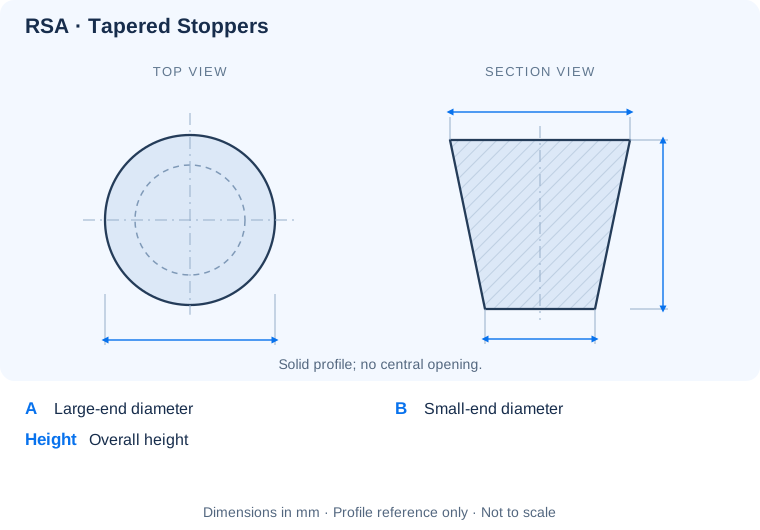
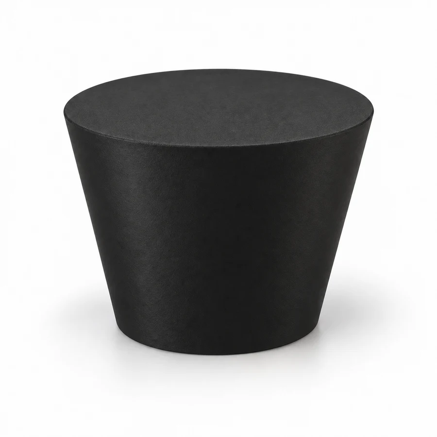
70 tapered stopper sizes. Compare the large-end diameter A, small-end diameter B and overall height with the opening and intended insertion depth.
| P/N | A | B | Height | Color | Material | Unit |
|---|---|---|---|---|---|---|
| RSA1.6-0.4-15.9 | 1.6 | 0.4 | 15.9 | Transparent | Silicone | mm |
| RSA2-0.5-19.1 | 2 | 0.5 | 19.1 | Transparent | Silicone | mm |
| RSA3.2-0.8-15.9 | 3.2 | 0.8 | 15.9 | Transparent | Silicone | mm |
| RSA3.2-1.6-15.9 | 3.2 | 1.6 | 15.9 | Transparent | Silicone | mm |
| RSA4.8-1.6-15.9 | 4.8 | 1.6 | 15.9 | Transparent | Silicone | mm |
| RSA4.8-1.6-19.1 | 4.8 | 1.6 | 19.1 | Transparent | Silicone | mm |
| RSA5.5-1.2-38.1 | 5.5 | 1.2 | 38.1 | Transparent | Silicone | mm |
| RSA6.4-3.2-19.1 | 6.4 | 3.2 | 19.1 | Transparent | Silicone | mm |
| RSA6.4-3.2-25.4 | 6.4 | 3.2 | 25.4 | Transparent | Silicone | mm |
| RSA8.7-4.8-15.9 | 8.7 | 4.8 | 15.9 | Transparent | Silicone | mm |
| RSA8.7-4.8-25.4 | 8.7 | 4.8 | 25.4 | Transparent | Silicone | mm |
| RSA9.2-6.2-12.8 | 9.2 | 6.2 | 12.8 | Transparent | Silicone | mm |
| RSA9.5-6.5-18.5 | 9.5 | 6.5 | 18.5 | Transparent | Silicone | mm |
| RSA11-8.5-17.5 | 11 | 8.5 | 17.5 | Transparent | Silicone | mm |
| RSA11.5-6.5-25 | 11.5 | 6.5 | 25 | Transparent | Silicone | mm |
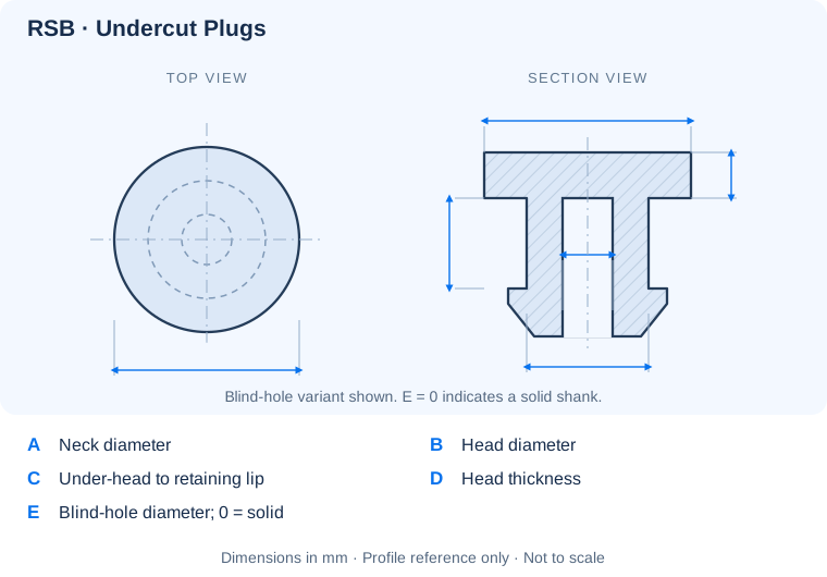
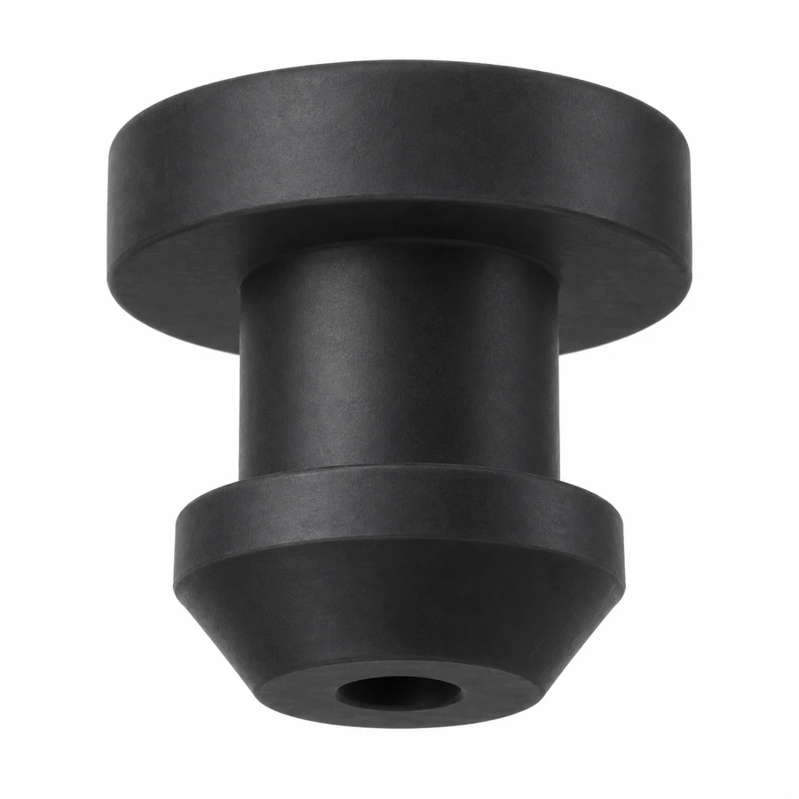
50 undercut plug sizes with a retaining lip. A is the neck diameter and C is the distance from the underside of the head to the upper face of the lip. E = 0 indicates a solid shank.
| P/N | A | B | C | D | E | Unit |
|---|---|---|---|---|---|---|
| RSB2.5-6-3 | 2.5 | 6 | 3 | 1.5 | 0 | mm |
| RSB3-7-3 | 3 | 7 | 3 | 2 | 0 | mm |
| RSB3.5-7.5-3 | 3.5 | 7.5 | 3 | 2 | 0 | mm |
| RSB3.6-7.5-6 | 3.6 | 7.5 | 6 | 2 | 0 | mm |
| RSB4-8-3 | 4 | 8 | 3 | 2 | 0 | mm |
| RSB4.5-8.5-3 | 4.5 | 8.5 | 3 | 2 | 2 | mm |
| RSB5-9-3 | 5 | 9 | 3 | 2 | 2.5 | mm |
| RSB5.5-9.5-3 | 5.5 | 9.5 | 3 | 2 | 3 | mm |
| RSB6-10-4 | 6 | 10 | 4 | 2 | 3.5 | mm |
| RSB6.5-10.5-4 | 6.5 | 10.5 | 4 | 2 | 4 | mm |
| RSB6.5-12-8 | 6.5 | 12 | 8 | 2 | 0 | mm |
| RSB6.7-8.7-5.3 | 6.7 | 8.7 | 5.3 | 1.3 | 4.1 | mm |
| RSB7-11-4 | 7 | 11 | 4 | 2 | 4.5 | mm |
| RSB7.5-11.5-4 | 7.5 | 11.5 | 4 | 2 | 5 | mm |
| RSB8-12-4 | 8 | 12 | 4 | 2 | 5.5 | mm |
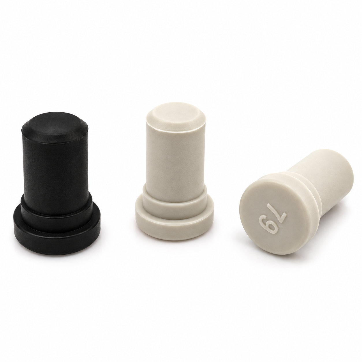
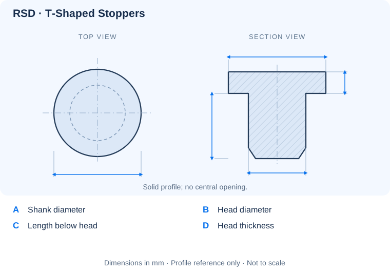
30 solid T-shaped stopper sizes. Compare shank diameter A and length C with the opening; head diameter B and thickness D define the top flange.
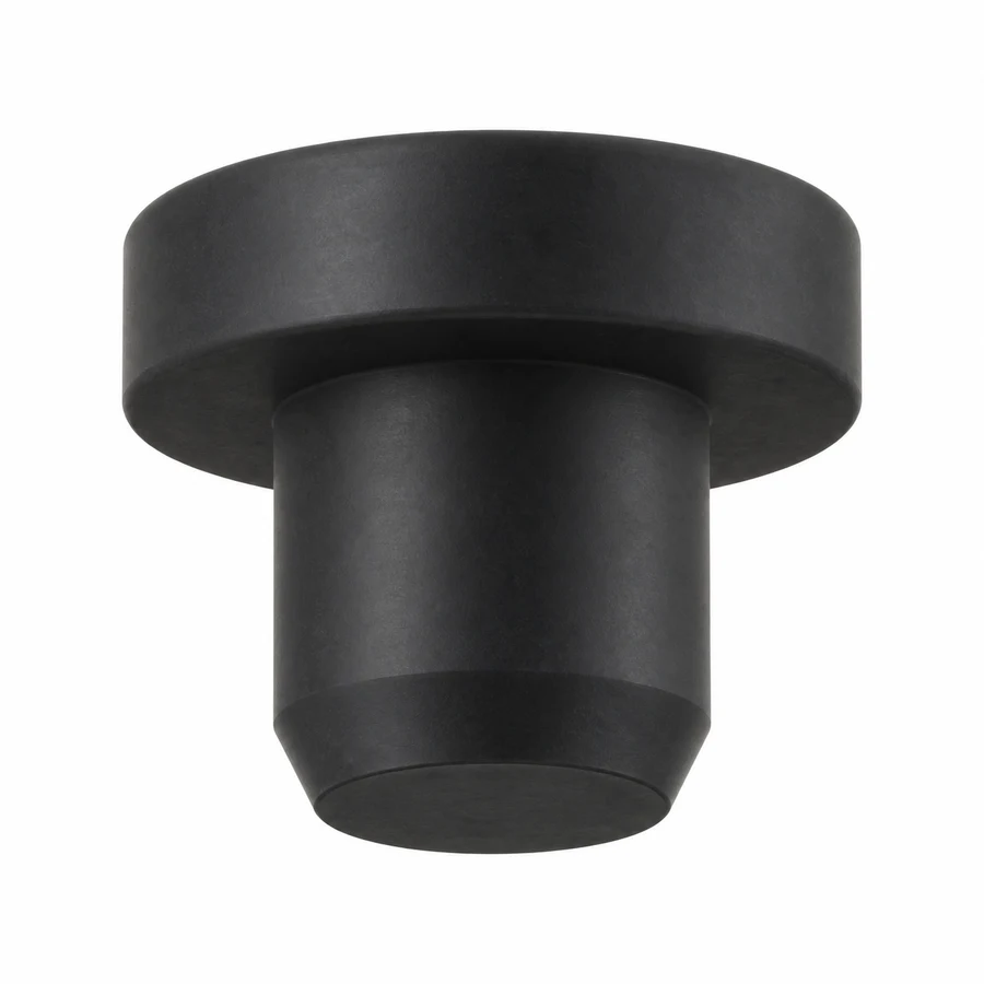
| P/N | A | B | C | D | Color | Material | Unit |
|---|---|---|---|---|---|---|---|
| RSD2.7-5.5-5 | 2.7 | 5.5 | 5 | 2 | Black, White | Silicone | mm |
| RSD3-7-7 | 3 | 7 | 7 | 2.2 | Black, White | Silicone | mm |
| RSD3.3-6.5-6 | 3.3 | 6.5 | 6 | 1.5 | Black, White | Silicone | mm |
| RSD3.5-6.5-6 | 3.5 | 6.5 | 6 | 2 | Black, White | Silicone | mm |
| RSD3.8-7-6 | 3.8 | 7 | 6 | 1.5 | Black, White | Silicone | mm |
| RSD4-9.5-7 | 4 | 9.5 | 7 | 2.5 | Black, White | Silicone | mm |
| RSD4.3-8-6 | 4.3 | 8 | 6 | 1.5 | Black, White | Silicone | mm |
| RSD4.5-7.5-6 | 4.5 | 7.5 | 6 | 2 | Black, White | Silicone | mm |
| RSD4.8-9-7 | 4.8 | 9 | 7 | 1.5 | Black, White | Silicone | mm |
| RSD5-12-8 | 5 | 12 | 8 | 2.8 | Black, White | Silicone | mm |
| RSD5.3-9.5-7 | 5.3 | 9.5 | 7 | 1.5 | Black, White | Silicone | mm |
| RSD5.5-8.5-7 | 5.5 | 8.5 | 7 | 2 | Black, White | Silicone | mm |
| RSD5.8-10-8 | 5.8 | 10 | 8 | 2 | Black, White | Silicone | mm |
| RSD6-13-8 | 6 | 13 | 8 | 3.5 | Black, White | Silicone | mm |
| RSD6.3-10.5-8 | 6.3 | 10.5 | 8 | 2 | Black, White | Silicone | mm |
Need a different fit? Share the opening dimensions, mating profile and intended use for a custom size.
Identify key dimensions, mating surfaces and quantity
Agree the compound and manufacturing approach
Review the fit and agreed requirements in the assembly
Manufacture and check against the approved requirements
Identify temperature, contact fluids and repeated movement.
Consider hardness together with wall thickness and support.
Check access, mating dimensions and the fitting sequence.
Yes. Show the receiving opening, contact surfaces and clearance limits. We can review the dimensions and retaining features around the intended fit.
Agree the critical dimensions, material, hardness, visible surfaces and sample requirements. Explain how the part is installed and which interfaces control its function.
A sample can help explain the structure. Compare it with the assembly because wear, swelling or compression may have changed its original dimensions.
The material, part geometry, tooling, quantity and finishing affect the quotation. Include the intended batch size and delivery destination when describing your requirements.
DISCUSS THIS COMPONENT
Share the fit, operating conditions and quantity with our manufacturing team.
EXPLORE RELATED DESIGNS
Explore similar part structures and applications for your next project.