Working conditions
Identify temperature, contact fluids and repeated movement.

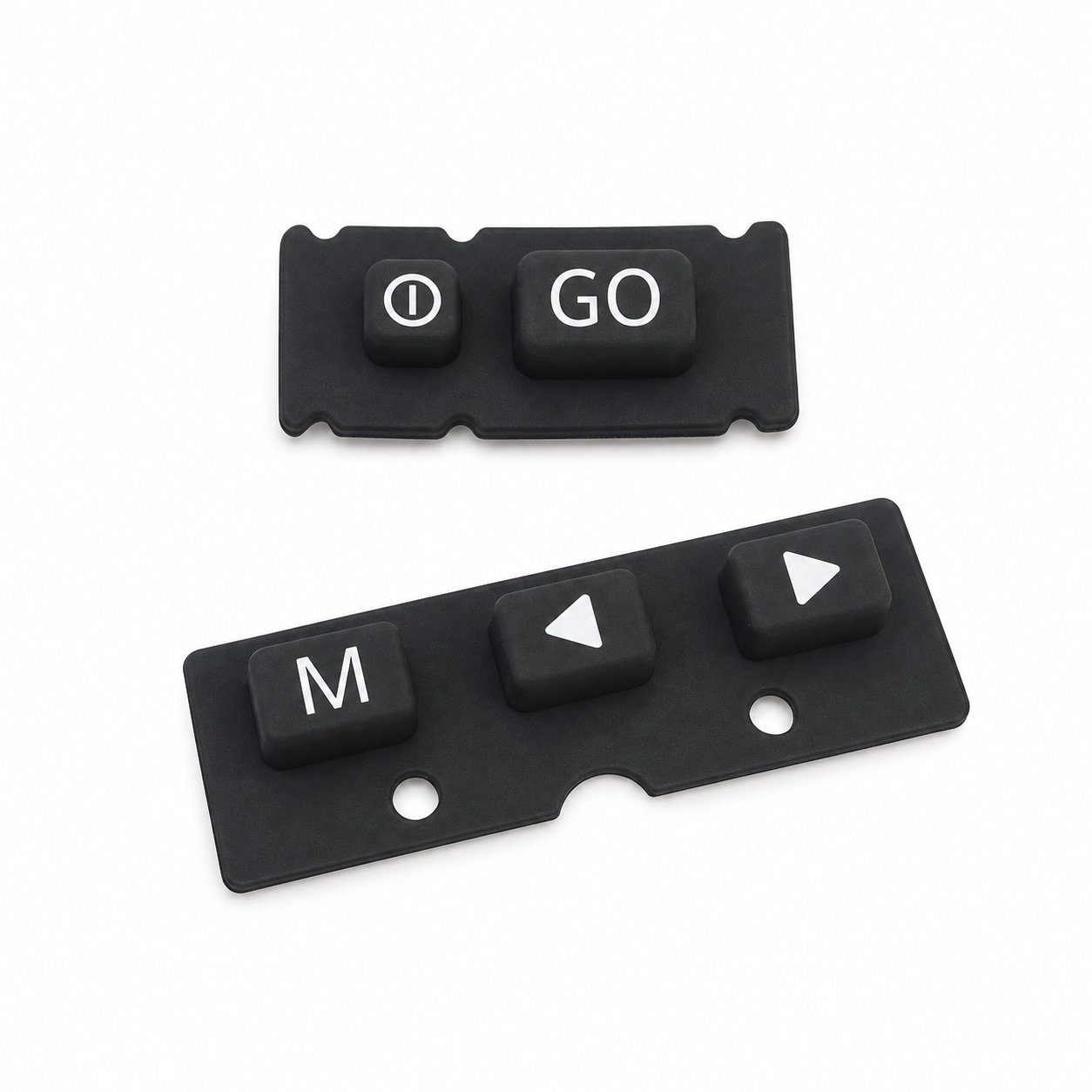
Custom manufacturing example · Custom made silicone PCB keypad Printed Circuit Board
CUSTOM RUBBER & SILICONE MANUFACTURING
A custom component for your assembly.
Define the mating surfaces, dimensions and working conditions. ETOL manufactures the part to the agreed design and material.
Share the part, its application and your estimated quantity.

Selected for the contact, temperature and movement
Define the visible surfaces and intended color
Develop holes, lips and walls around the mating parts
Match the attachment and installation method
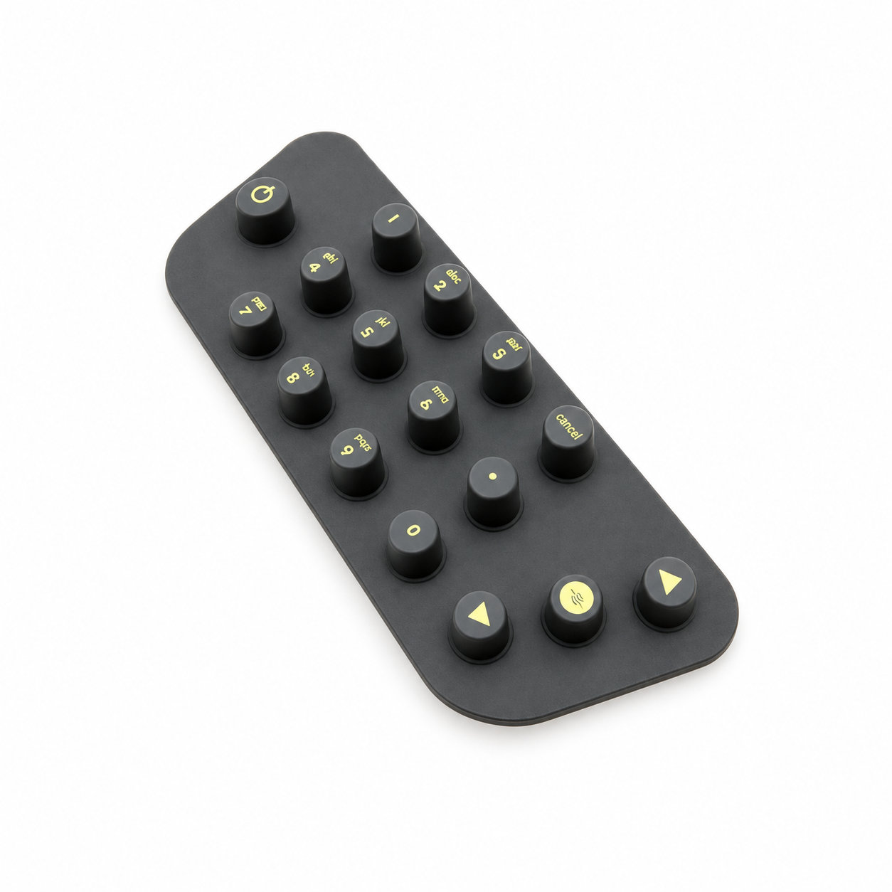
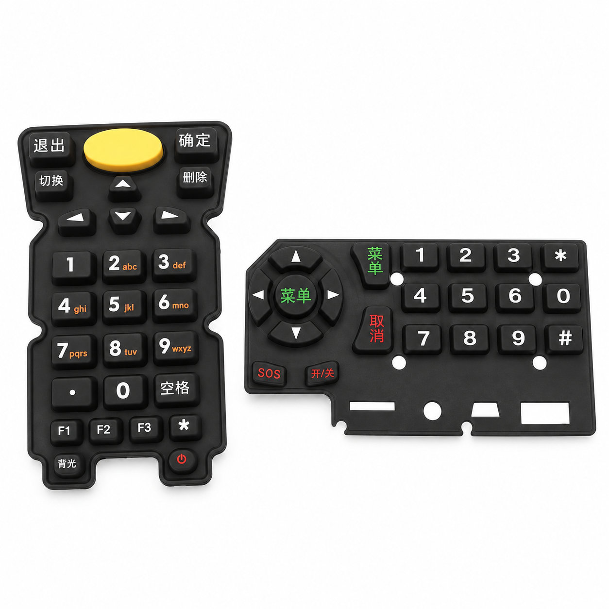
A PCB keypad provides a flexible silicone control surface designed around a matching printed circuit board. The molded keys, contact positions and locating features should agree with the board layout and front housing. The board is part of the fit definition rather than only a surface placed beneath the rubber.
Check the distance between the board and the visible keys after the enclosure is secured. Support posts or fasteners can influence that spacing across the layout. Each key needs its intended resting clearance and movement without the panel holding it partly depressed.
Align the common keypad before testing individual buttons. A shifted edge can move several contacts together, while a warped support can make one area respond differently from another. Keep the underside clean and avoid introducing adhesive near the switching region during assembly. During service, restore the original board seating and fastening conditions before judging a key fault. A revised board or enclosure requires a corresponding fit review, even if the printed function layout is unchanged. The replacement keypad should preserve both the visible controls and the contact geometry that operates the intended circuit.
Photos illustrate structure or material only. Each key needs its intended resting clearance and movement without the panel holding it partly depressed. ETOL directly manufactures custom-shaped silicone and rubber parts to your requirements.
Identify key dimensions, mating surfaces and quantity
Agree the compound and manufacturing approach
Review the fit and agreed requirements in the assembly
Manufacture and check against the approved requirements
Identify temperature, contact fluids and repeated movement.
Consider hardness together with wall thickness and support.
Check access, mating dimensions and the fitting sequence.
Yes. Show the receiving opening, contact surfaces and clearance limits. We can review the dimensions and retaining features around the intended fit.
Agree the critical dimensions, material, hardness, visible surfaces and sample requirements. Explain how the part is installed and which interfaces control its function.
A sample can help explain the structure. Compare it with the assembly because wear, swelling or compression may have changed its original dimensions.
The material, part geometry, tooling, quantity and finishing affect the quotation. Include the intended batch size and delivery destination when describing your requirements.
DISCUSS THIS COMPONENT
Share the fit, operating conditions and quantity with our manufacturing team.
EXPLORE RELATED DESIGNS
Explore similar part structures and applications for your next project.