Working conditions
Identify temperature, contact fluids and repeated movement.

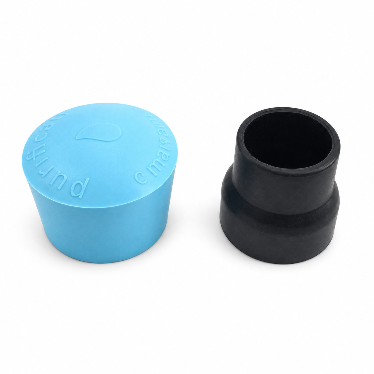
Custom manufacturing example · Silicone rubber tip cap rubber feet cover
CUSTOM RUBBER & SILICONE MANUFACTURING
A custom component for your assembly.
Define the mating surfaces, dimensions and working conditions. ETOL manufactures the part to the agreed design and material.
Share the part, its application and your estimated quantity.

Selected for the contact, temperature and movement
Define the visible surfaces and intended color
Develop holes, lips and walls around the mating parts
Match the attachment and installation method
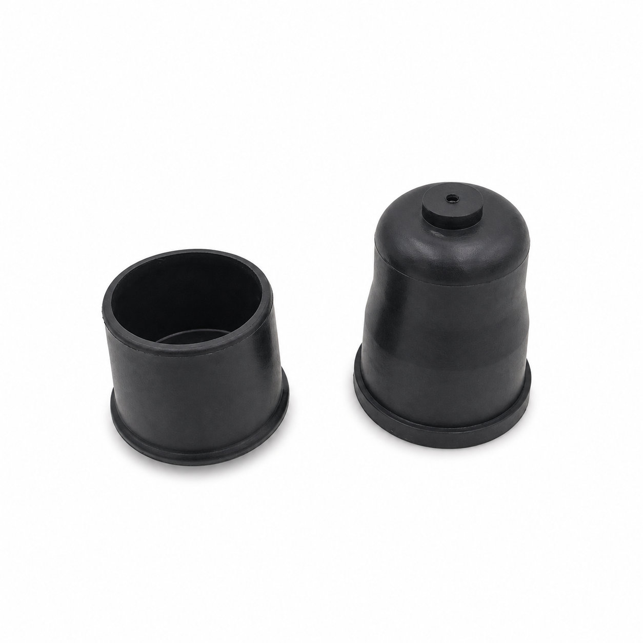
A silicone rubber tip cap can cover the end of a supporting component and create a flexible foot at its contact point. In a compact appliance or electronic assembly, this covered end may help separate the rigid component from the supporting surface. The cap's installed height and cavity depth are important because they determine where the equipment sits once the part is fitted.
Begin with the complete support arrangement. Measure the exposed tip, the length that enters the cap and the clearance required beneath the housing. If several caps support one assembly, evaluate their fitted heights together. Small differences in how deeply each tip seats can cause uneven contact, even when the loose caps appear identical. Any nearby ventilation opening, cable exit or access cover should also remain unobstructed.
ETOL lists custom dimensions, color, material and hardness for this product. The selected formulation should be reviewed for the actual contact conditions, including the supporting surface, normal equipment weight and any cleaning exposure. A softer feel does not automatically provide a better support: the cap must retain its intended geometry sufficiently for the surrounding assembly. Sample evaluation should therefore include the equipment standing in its normal position.
Fit the silicone rubber tip cap straight onto a clean mating end and check its seating without cutting or stretching the entrance unnecessarily. Do not use the cap to conceal a damaged support that needs repair. After assembly, verify that the housing is stable and the expected clearance remains available. Examine the base for wear and the interior for trapped particles when the cap is removed during maintenance. Send ETOL the support drawing and an installed section view when requesting a custom version; those details describe the working fit more clearly than an exterior size alone.
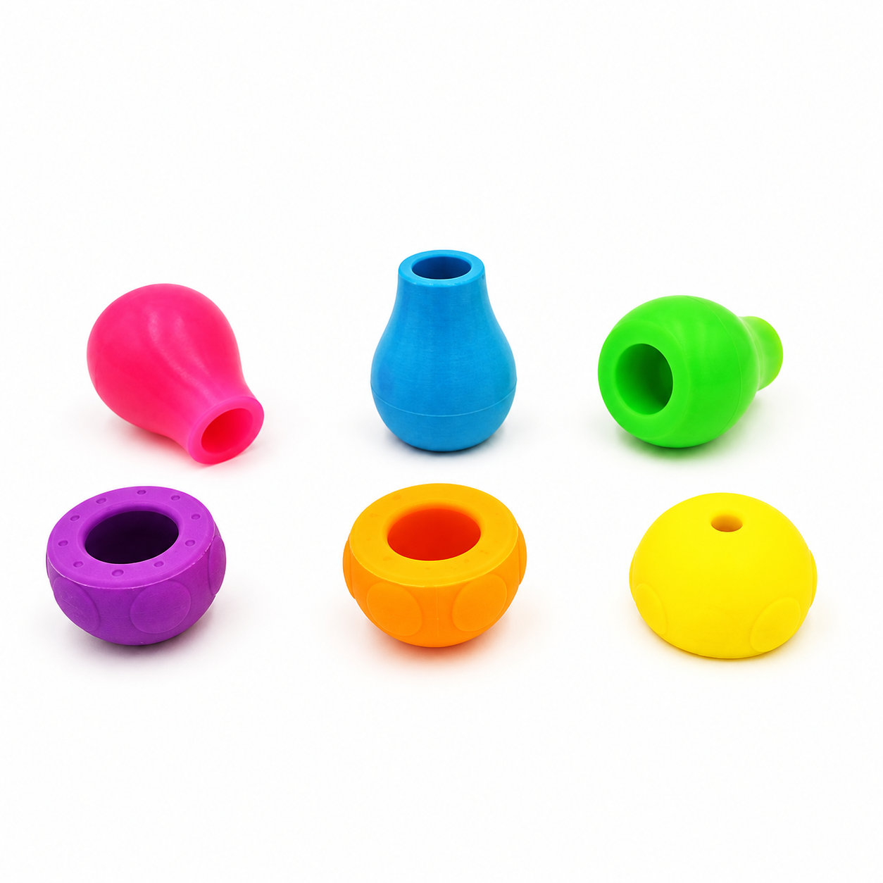
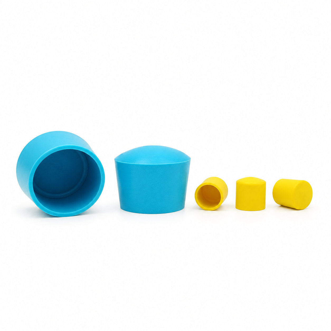
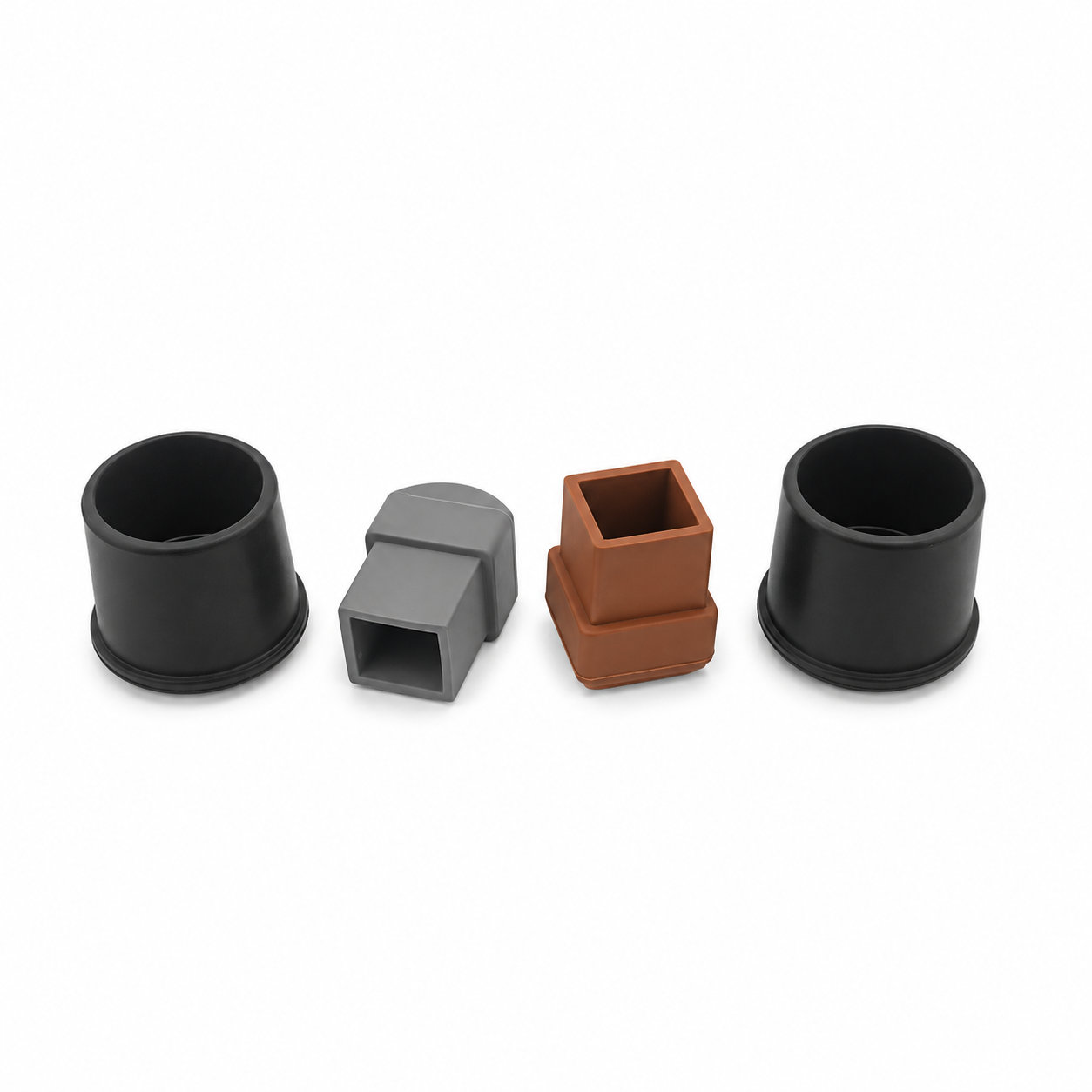
Photos illustrate structure or material only. In a compact appliance or electronic assembly, this covered end may help separate the rigid component from the supporting surface. ETOL directly manufactures custom-shaped silicone and rubber parts to your requirements.
FIND THE RIGHT FIT
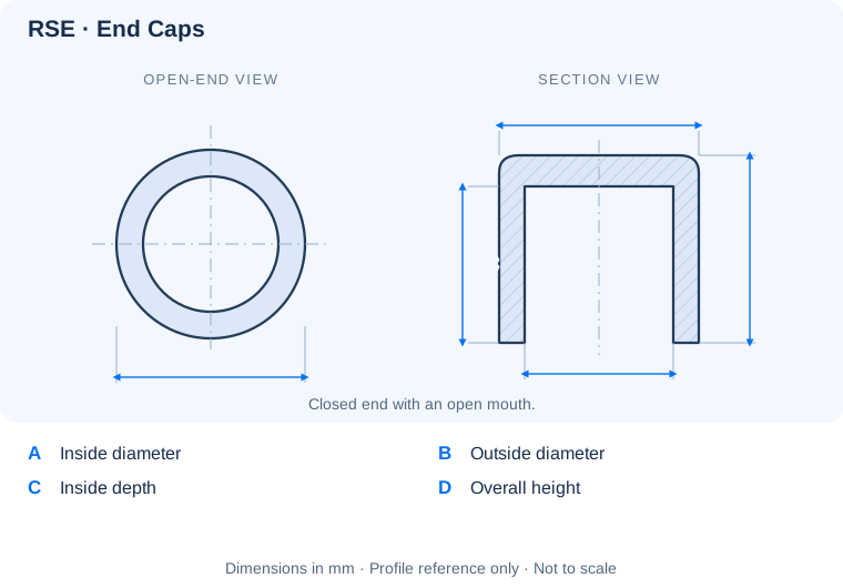
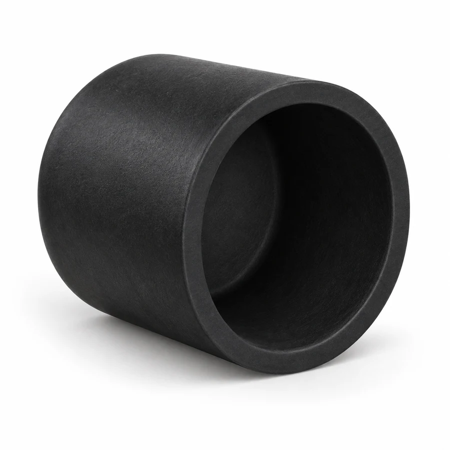
Compare inside diameter A with the outside of the part being covered. Check inside depth C and overall dimensions B and D for available clearance. These RSE references show a round cap with one closed end.
43 closed-end cap sizes. A is the inside diameter and C is the usable internal depth; B and D describe the outside envelope.
| P/N | A | B | C | D | Color | Unit |
|---|---|---|---|---|---|---|
| RSE3.7-7-9 | 3.7 | 7 | 9 | 11 | black,white | mm |
| RSE4.7-8-9 | 4.7 | 8 | 9 | 11 | black,white | mm |
| RSE5.7-9-10 | 5.7 | 9 | 10 | 12 | black,white | mm |
| RSE6.7-10-10 | 6.7 | 10 | 10 | 12 | black,white | mm |
| RSE7.7-11-11 | 7.7 | 11 | 11 | 13 | black,white | mm |
| RSE8.7-12-12 | 8.7 | 12 | 12 | 14 | black,white | mm |
| RSE9.7-14-13 | 9.7 | 14 | 13 | 15 | black,white | mm |
| RSE10.7-15-14 | 10.7 | 15 | 14 | 16 | black,white | mm |
| RSE11.7-16-15 | 11.7 | 16 | 15 | 17 | black,white | mm |
| RSE12.7-17-15 | 12.7 | 17 | 15 | 18 | black,white | mm |
| RSE13.7-18-15 | 13.7 | 18 | 15 | 18 | black,white | mm |
| RSE14.7-19-15 | 14.7 | 19 | 15 | 18 | black,white | mm |
| RSE15.7-20-16 | 15.7 | 20 | 16 | 19 | black,white | mm |
| RSE16.7-21-16 | 16.7 | 21 | 16 | 19 | black,white | mm |
| RSE17.7-22-16 | 17.7 | 22 | 16 | 19 | black,white | mm |
Need a different fit? Share the opening dimensions, mating profile and intended use for a custom size.
Identify key dimensions, mating surfaces and quantity
Agree the compound and manufacturing approach
Review the fit and agreed requirements in the assembly
Manufacture and check against the approved requirements
Identify temperature, contact fluids and repeated movement.
Consider hardness together with wall thickness and support.
Check access, mating dimensions and the fitting sequence.
Yes. Show the receiving opening, contact surfaces and clearance limits. We can review the dimensions and retaining features around the intended fit.
Agree the critical dimensions, material, hardness, visible surfaces and sample requirements. Explain how the part is installed and which interfaces control its function.
A sample can help explain the structure. Compare it with the assembly because wear, swelling or compression may have changed its original dimensions.
The material, part geometry, tooling, quantity and finishing affect the quotation. Include the intended batch size and delivery destination when describing your requirements.
DISCUSS THIS COMPONENT
Share the fit, operating conditions and quantity with our manufacturing team.
EXPLORE RELATED DESIGNS
Explore similar part structures and applications for your next project.