Working conditions
Identify temperature, contact fluids and repeated movement.

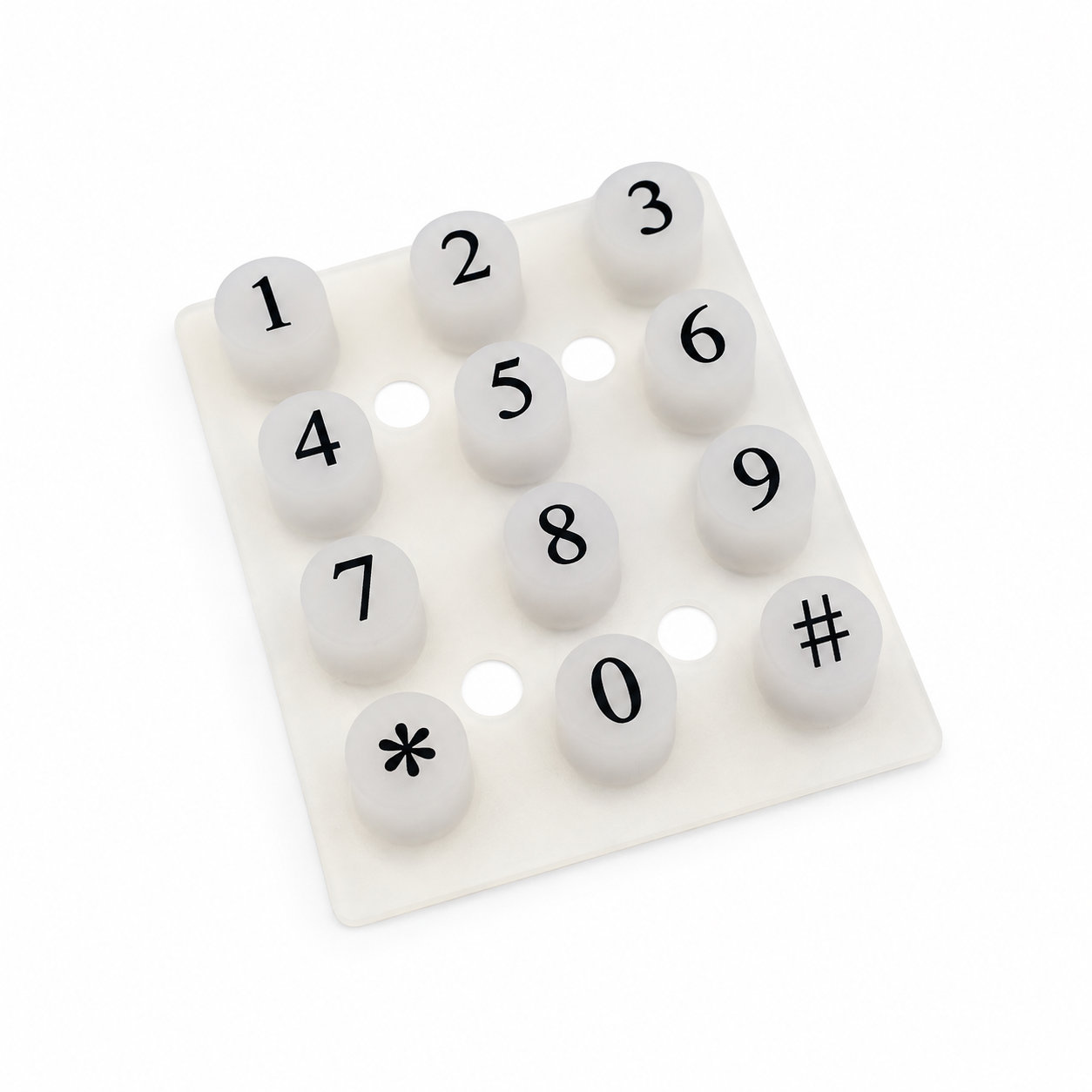
Custom manufacturing example · Customized transparent silicone rubber keypad buttons with conductive
CUSTOM RUBBER & SILICONE MANUFACTURING
A custom component for your assembly.
Define the mating surfaces, dimensions and working conditions. ETOL manufactures the part to the agreed design and material.
Share the part, its application and your estimated quantity.

Selected for the contact, temperature and movement
Define the visible surfaces and intended color
Develop holes, lips and walls around the mating parts
Match the attachment and installation method
Transparent silicone rubber keypad buttons combine a visually open material choice with conductive features in the intended input arrangement. The conductive region and any underlying board will influence what can be seen through the button. Transparency should therefore be evaluated with the actual construction rather than assumed to produce a uniformly clear or illuminated key.
Coordinate the molded thickness, contact position and visible artwork with the housing. A clear-looking button still needs the correct travel and rest gap above its electrical target. The surrounding panel must leave the flexible sections free to move while maintaining registration.
Check both appearance and operation after assembly. Any lighting effect depends on the complete optical arrangement, and no particular contact resistance is established by the product category. Handle the visible surface carefully to avoid scratches and keep the underside contact areas free of residue. During reassembly, restore the locating features so a change in board or sheet position does not alter the button's intended electrical contact or visible alignment.
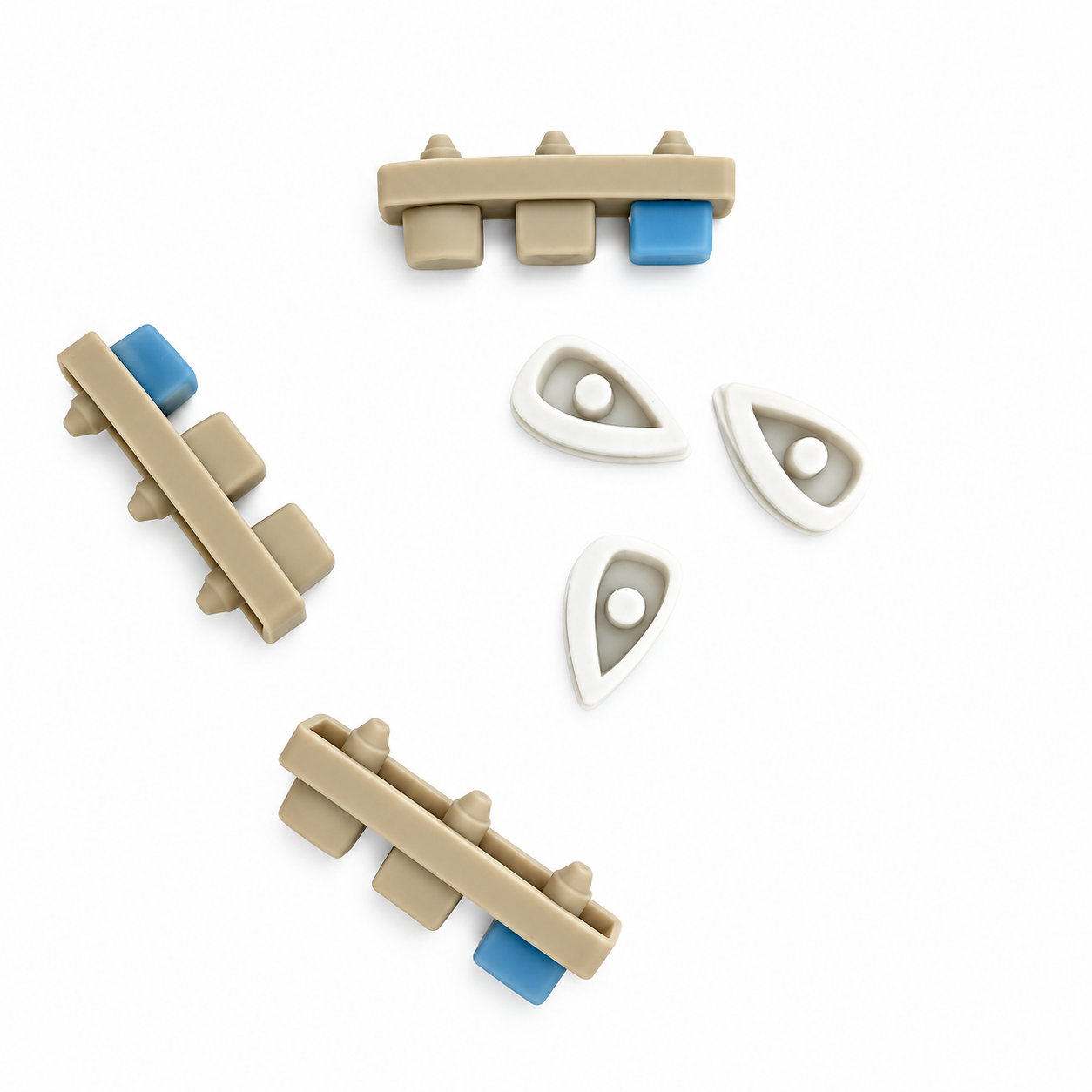
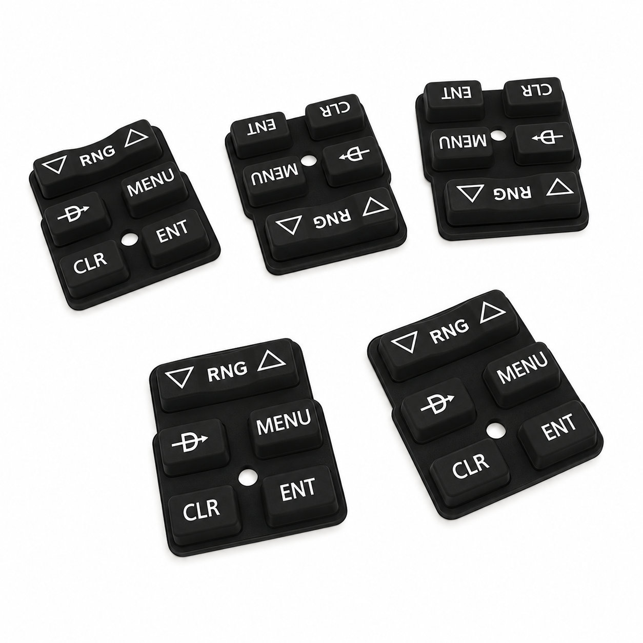
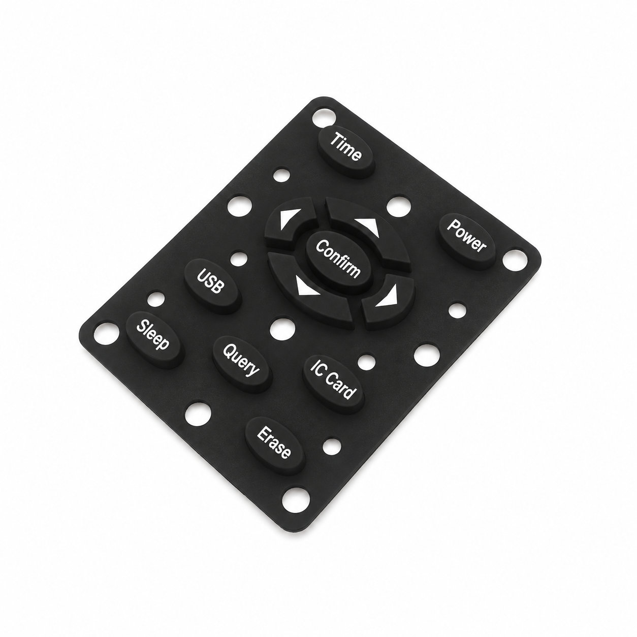
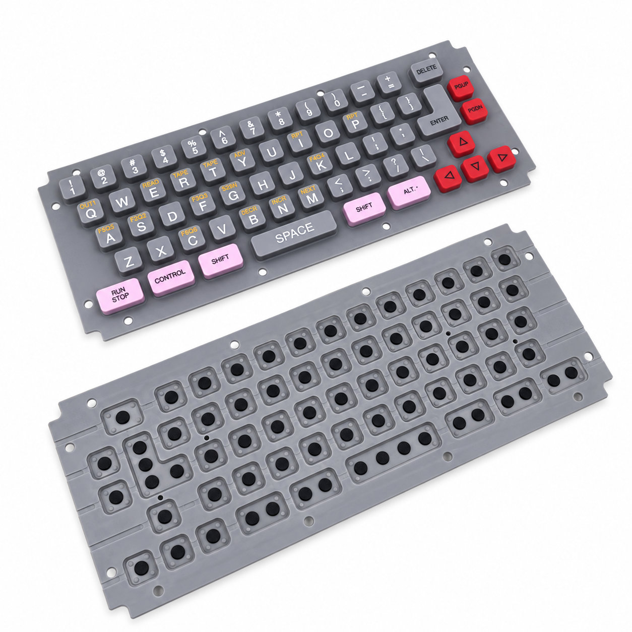
Photos illustrate structure or material only. During reassembly, restore the locating features so a change in board or sheet position does not alter the button's intended electrical contact or visible alignment. ETOL directly manufactures custom-shaped silicone and rubber parts to your requirements.
Identify key dimensions, mating surfaces and quantity
Agree the compound and manufacturing approach
Review the fit and agreed requirements in the assembly
Manufacture and check against the approved requirements
Identify temperature, contact fluids and repeated movement.
Consider hardness together with wall thickness and support.
Check access, mating dimensions and the fitting sequence.
Yes. Show the receiving opening, contact surfaces and clearance limits. We can review the dimensions and retaining features around the intended fit.
Agree the critical dimensions, material, hardness, visible surfaces and sample requirements. Explain how the part is installed and which interfaces control its function.
A sample can help explain the structure. Compare it with the assembly because wear, swelling or compression may have changed its original dimensions.
The material, part geometry, tooling, quantity and finishing affect the quotation. Include the intended batch size and delivery destination when describing your requirements.
DISCUSS THIS COMPONENT
Share the fit, operating conditions and quantity with our manufacturing team.
EXPLORE RELATED DESIGNS
Explore similar part structures and applications for your next project.