Working conditions
Identify temperature, contact fluids and repeated movement.

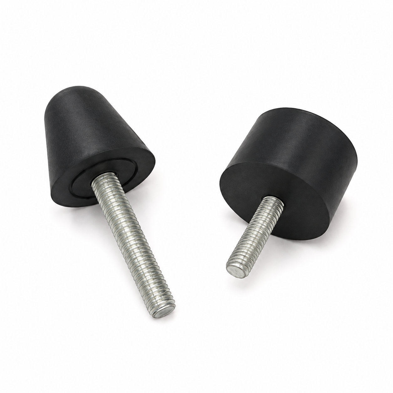
Custom manufacturing example · Rubber Shock and Vibration Mounts /Engine Vibration Isolators
CUSTOM RUBBER & SILICONE MANUFACTURING
A custom component for your assembly.
Define the mating surfaces, dimensions and working conditions. ETOL manufactures the part to the agreed design and material.
Share the part, its application and your estimated quantity.

Selected for the contact, temperature and movement
Define the visible surfaces and intended color
Develop holes, lips and walls around the mating parts
Match the attachment and installation method
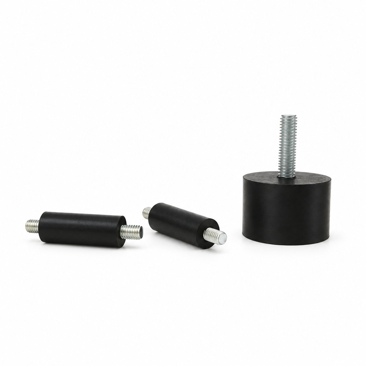
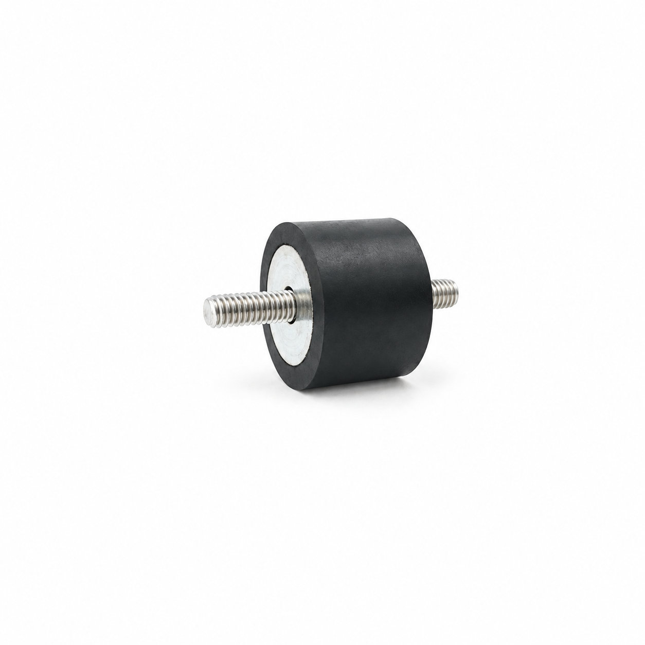
Rubber shock and vibration mounts provide compliant interfaces within an engine support arrangement. The custom rubber profile and attachment geometry should be selected around the engine mass, mounting positions, and expected movement. The mounts operate as part of a system that includes the supporting frame and connected components.
Consider the engine's position both at rest and during operation. The mounts need the intended clearance around them, and the support arrangement should preserve the required alignment of connected parts. Hoses, wiring, exhaust components, or other connections should not unintentionally restrain the movement the mounting design permits. A rigid contact elsewhere in the assembly can also change the vibration path.
Select the rubber formulation for the local temperature and fluid exposure at each mounting location. Assess the finished mounting arrangement through the relevant operating conditions, including changes associated with starting or stopping. Size and hardness alone do not define an engine load capacity or isolation result.
During maintenance, inspect the rubber, attachment points, and nearby clearances together. Uneven deformation or a changed resting position can affect more than one connection. A replacement should preserve the intended mount geometry and material assignment, followed by a check of the complete engine support and connected routes in their assembled state.
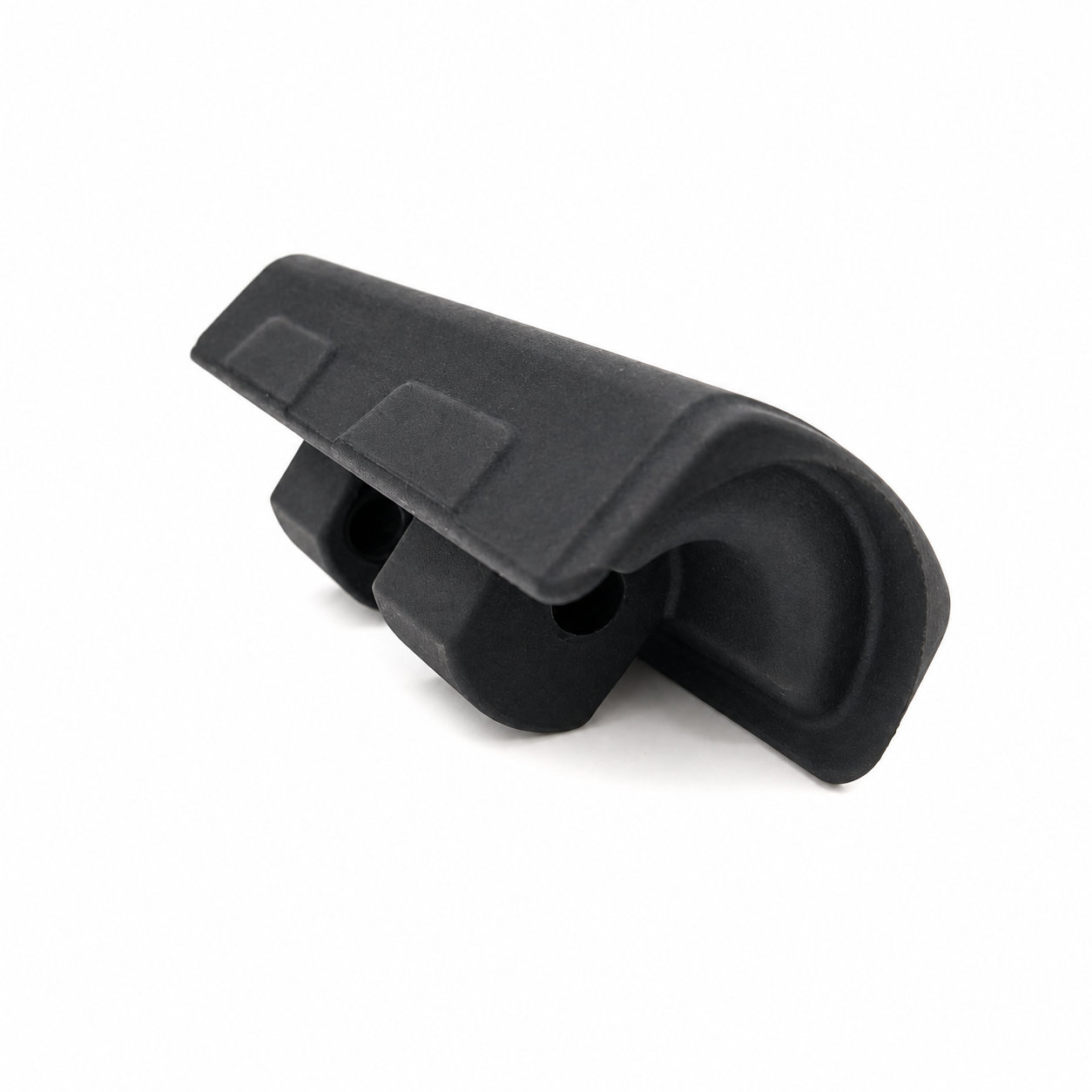
Photos illustrate structure or material appearance only. The custom rubber profile and attachment geometry should be selected around the engine mass, mounting positions, and expected movement. ETOL directly manufactures custom-shaped silicone and rubber parts to your requirements.
FIND THE RIGHT FIT
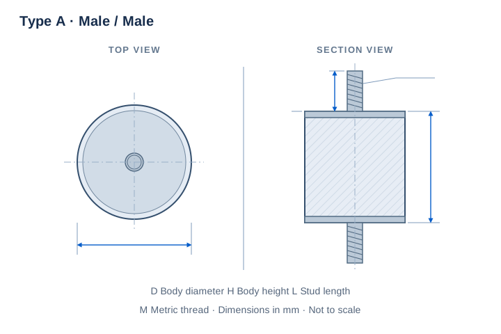
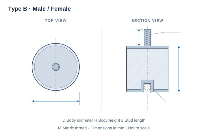
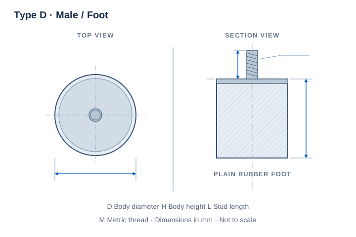
Choose a connection type, then compare body dimensions and metric threads. D, H and L are in millimeters; H excludes projecting studs. The M designation identifies the metric thread.
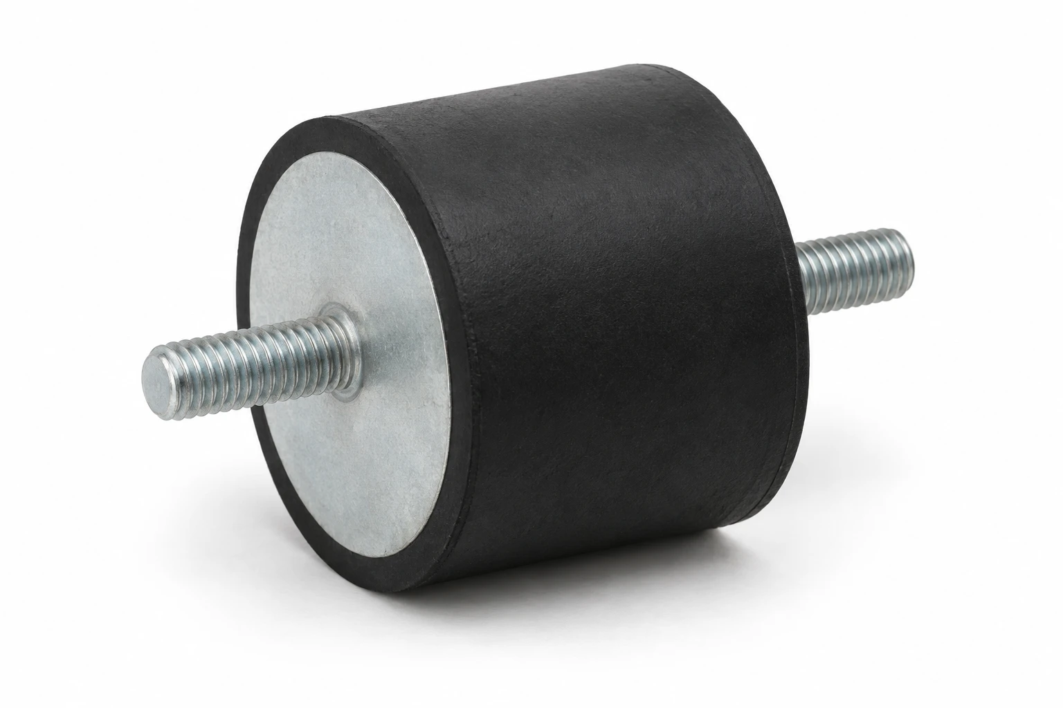
157 sizes with a male stud at each end. Compare body diameter D, body height H, thread size and projecting stud length L.
| P/N | D | H | Thread | L | Unit |
|---|---|---|---|---|---|
| AVMM-88M36 | 8 | 8 | M3 | 6 | mm |
| AVMM-88M38 | 8 | 8 | M3 | 8 | mm |
| AVMM-88M310 | 8 | 8 | M3 | 10 | mm |
| AVMM-810M38 | 8 | 10 | M3 | 8 | mm |
| AVMM-108M36 | 10 | 8 | M3 | 6 | mm |
| AVMM-108M310 | 10 | 8 | M3 | 10 | mm |
| AVMM-108M46 | 10 | 8 | M4 | 6 | mm |
| AVMM-108M410 | 10 | 8 | M4 | 10 | mm |
| AVMM-1010M38 | 10 | 10 | M3 | 8 | mm |
| AVMM-1010M46 | 10 | 10 | M4 | 6 | mm |
| AVMM-1010M410 | 10 | 10 | M4 | 10 | mm |
| AVMM-1015M36 | 10 | 15 | M3 | 6 | mm |
| AVMM-1015M46 | 10 | 15 | M4 | 6 | mm |
| AVMM-1015M410 | 10 | 15 | M4 | 10 | mm |
| AVMM-158M410 | 15 | 8 | M4 | 10 | mm |
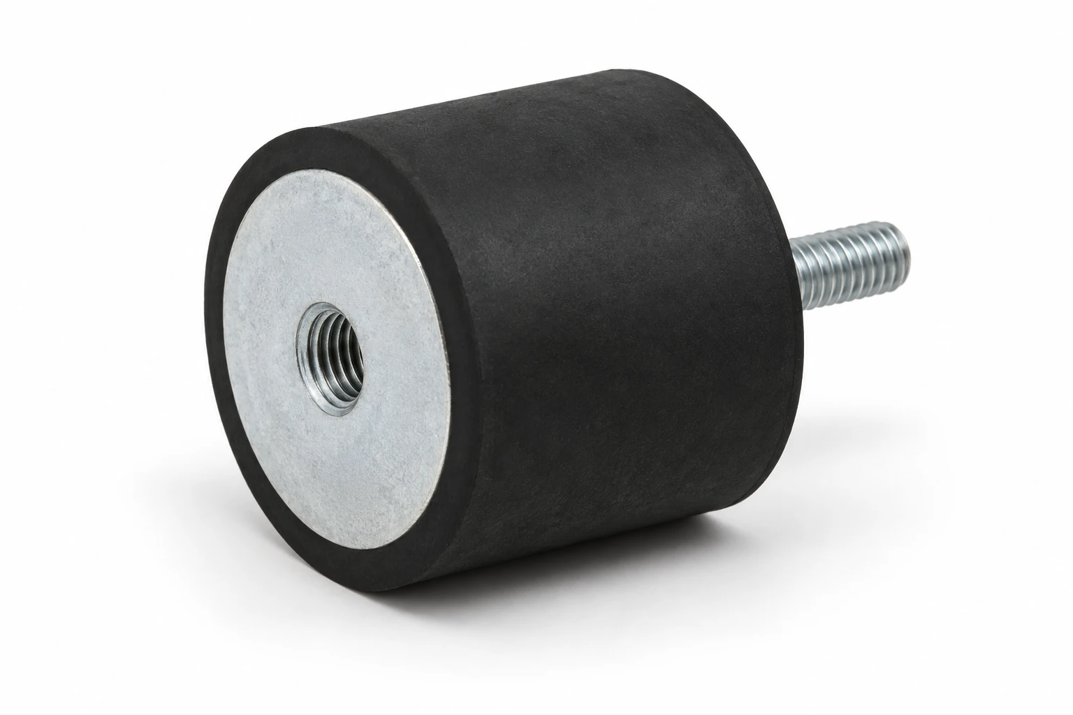
175 sizes combining one male stud and one female insert. Use D and H for the body envelope and L for the exposed stud.
| P/N | D | H | Thread | L | Unit |
|---|---|---|---|---|---|
| AVMF-88M36 | 8 | 8 | M3 | 6 | mm |
| AVMF-88M38 | 8 | 8 | M3 | 8 | mm |
| AVMF-88M310 | 8 | 8 | M3 | 10 | mm |
| AVMF-108M46 | 10 | 8 | M4 | 6 | mm |
| AVMF-108M410 | 10 | 8 | M4 | 10 | mm |
| AVMF-1010M36 | 10 | 10 | M3 | 6 | mm |
| AVMF-1010M38 | 10 | 10 | M3 | 8 | mm |
| AVMF-1010M310 | 10 | 10 | M3 | 10 | mm |
| AVMF-1010M46 | 10 | 10 | M4 | 6 | mm |
| AVMF-1010M410 | 10 | 10 | M4 | 10 | mm |
| AVMF-1015M36 | 10 | 15 | M3 | 6 | mm |
| AVMF-1015M310 | 10 | 15 | M3 | 10 | mm |
| AVMF-1015M46 | 10 | 15 | M4 | 6 | mm |
| AVMF-1015M410 | 10 | 15 | M4 | 10 | mm |
| AVMF-158M410 | 15 | 8 | M4 | 10 | mm |
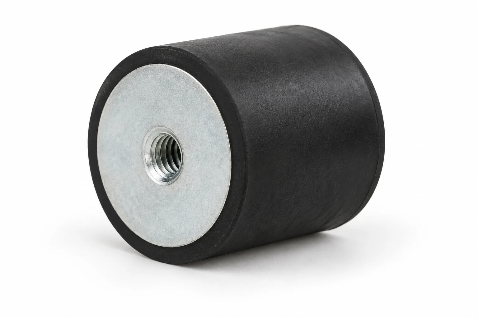
89 sizes with female threads at both ends. Match body diameter D, body height H and the metric thread size.

| P/N | D | H | Thread | Unit |
|---|---|---|---|---|
| AVFF-88M3 | 8 | 8 | M3 | mm |
| AVFF-1010M3 | 10 | 10 | M3 | mm |
| AVFF-1010M4 | 10 | 10 | M4 | mm |
| AVFF-1015M3 | 10 | 15 | M3 | mm |
| AVFF-1015M4 | 10 | 15 | M4 | mm |
| AVFF-1515M4 | 15 | 15 | M4 | mm |
| AVFF-1515M5 | 15 | 15 | M5 | mm |
| AVFF-1520M4 | 15 | 20 | M4 | mm |
| AVFF-1520M5 | 15 | 20 | M5 | mm |
| AVFF-1530M4 | 15 | 30 | M4 | mm |
| AVFF-1530M5 | 15 | 30 | M5 | mm |
| AVFF-2015M6 | 20 | 15 | M6 | mm |
| AVFF-2020M5 | 20 | 20 | M5 | mm |
| AVFF-2020M6 | 20 | 20 | M6 | mm |
| AVFF-2025M6 | 20 | 25 | M6 | mm |
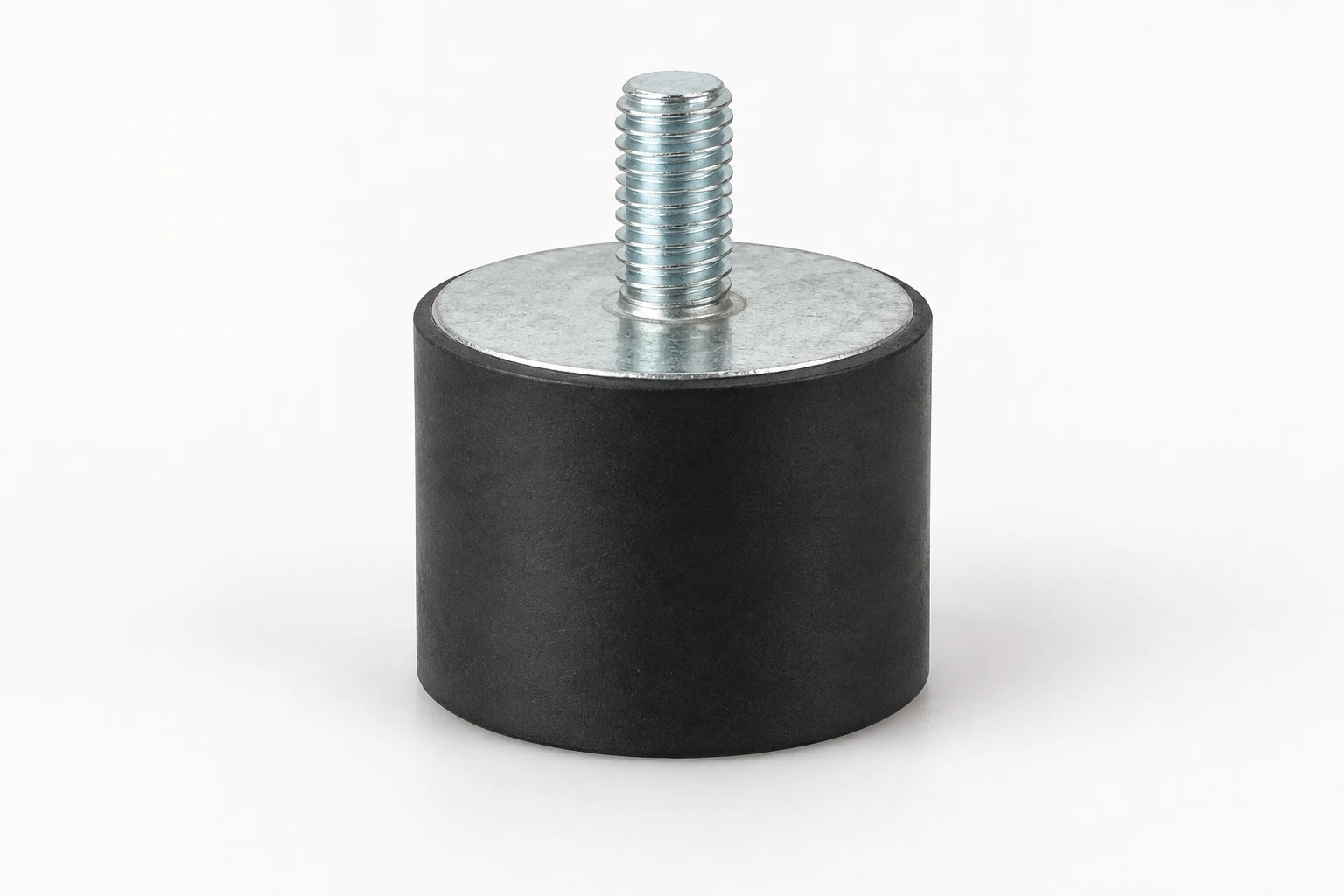
137 sizes with a single male stud and a plain rubber foot. Check D for the footprint, H for body height and L for stud projection.
| P/N | D | H | Thread | L | Unit |
|---|---|---|---|---|---|
| AVSM-88M36 | 8 | 8 | M3 | 6 | mm |
| AVSM-88M310 | 8 | 8 | M3 | 10 | mm |
| AVSM-108M46 | 10 | 8 | M4 | 6 | mm |
| AVSM-108M410 | 10 | 8 | M4 | 10 | mm |
| AVSM-1010M310 | 10 | 10 | M3 | 10 | mm |
| AVSM-1010M46 | 10 | 10 | M4 | 6 | mm |
| AVSM-1010M410 | 10 | 10 | M4 | 10 | mm |
| AVSM-1015M310 | 10 | 15 | M3 | 10 | mm |
| AVSM-1015M46 | 10 | 15 | M4 | 6 | mm |
| AVSM-1015M410 | 10 | 15 | M4 | 10 | mm |
| AVSM-158M410 | 15 | 8 | M4 | 10 | mm |
| AVSM-158M415 | 15 | 8 | M4 | 15 | mm |
| AVSM-158M510 | 15 | 8 | M5 | 10 | mm |
| AVSM-1510M410 | 15 | 10 | M4 | 10 | mm |
| AVSM-1510M415 | 15 | 10 | M4 | 15 | mm |
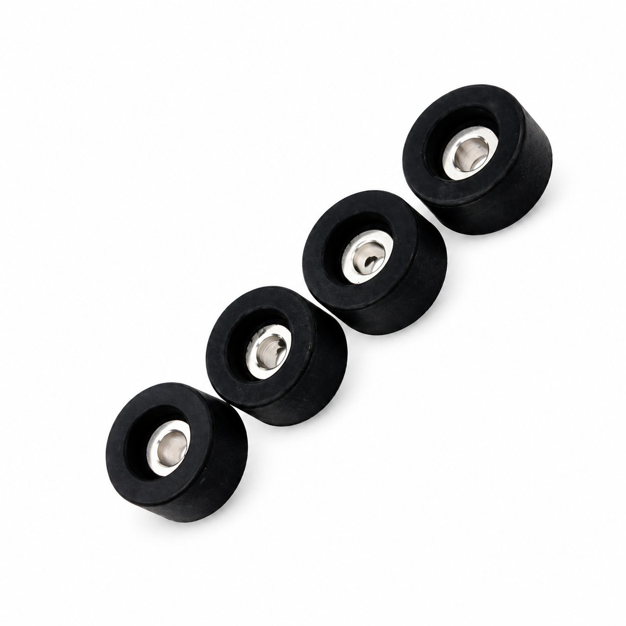
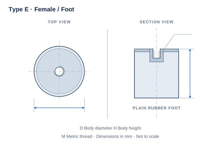
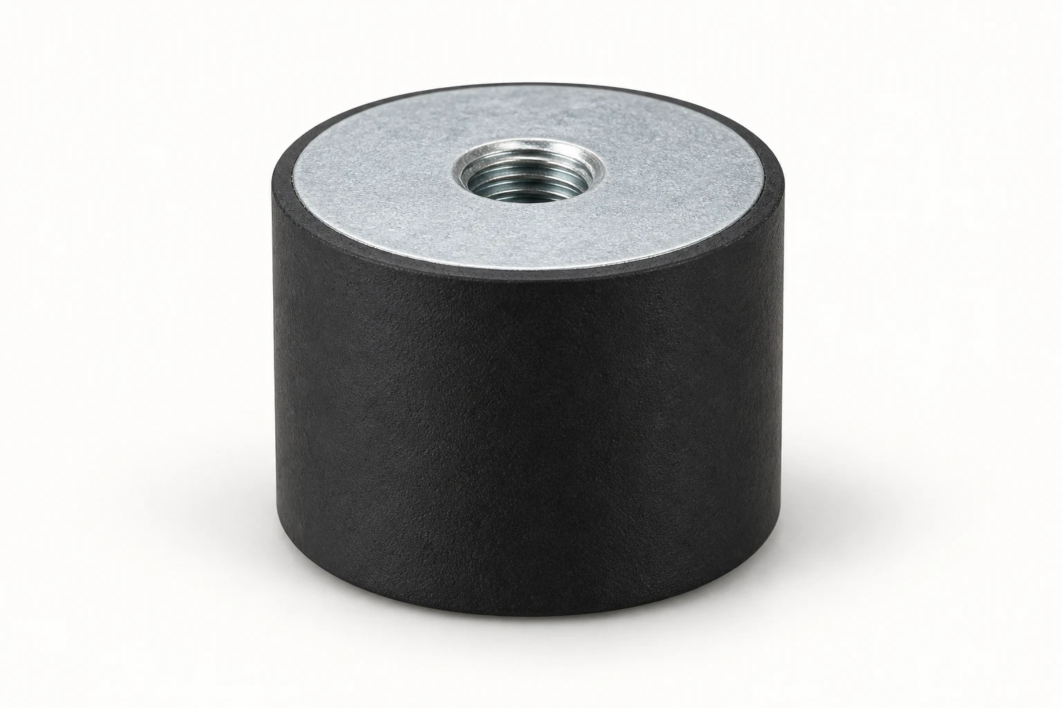
80 sizes with a female top insert and a plain rubber foot. Compare diameter D, height H and the recessed thread size.
| P/N | D | H | Thread | Unit |
|---|---|---|---|---|
| AVSF-88M3 | 8 | 8 | M3 | mm |
| AVSF-108M3 | 10 | 8 | M3 | mm |
| AVSF-108M4 | 10 | 8 | M4 | mm |
| AVSF-1010M3 | 10 | 10 | M3 | mm |
| AVSF-1010M4 | 10 | 10 | M4 | mm |
| AVSF-1015M3 | 10 | 15 | M3 | mm |
| AVSF-1015M4 | 10 | 15 | M4 | mm |
| AVSF-158M4 | 15 | 8 | M4 | mm |
| AVSF-1510M4 | 15 | 10 | M4 | mm |
| AVSF-1510M5 | 15 | 10 | M5 | mm |
| AVSF-1515M4 | 15 | 15 | M4 | mm |
| AVSF-1515M5 | 15 | 15 | M5 | mm |
| AVSF-1520M4 | 15 | 20 | M4 | mm |
| AVSF-1520M5 | 15 | 20 | M5 | mm |
| AVSF-1530M4 | 15 | 30 | M4 | mm |
Can't find the right size? Contact us for custom dimensions tailored to your requirements.
Identify key dimensions, mating surfaces and quantity
Agree the compound and manufacturing approach
Review the fit and agreed requirements in the assembly
Manufacture and check against the approved requirements
Identify temperature, contact fluids and repeated movement.
Consider hardness together with wall thickness and support.
Check access, mating dimensions and the fitting sequence.
Yes. Show the receiving opening, contact surfaces and clearance limits. We can review the dimensions and retaining features around the intended fit.
Agree the critical dimensions, material, hardness, visible surfaces and sample requirements. Explain how the part is installed and which interfaces control its function.
A sample can help explain the structure. Compare it with the assembly because wear, swelling or compression may have changed its original dimensions.
The material, part geometry, tooling, quantity and finishing affect the quotation. Include the intended batch size and delivery destination when describing your requirements.
DISCUSS THIS COMPONENT
Share the fit, operating conditions and quantity with our manufacturing team.
EXPLORE RELATED DESIGNS
Explore similar part structures and applications for your next project.