Working conditions
Identify temperature, contact fluids and repeated movement.

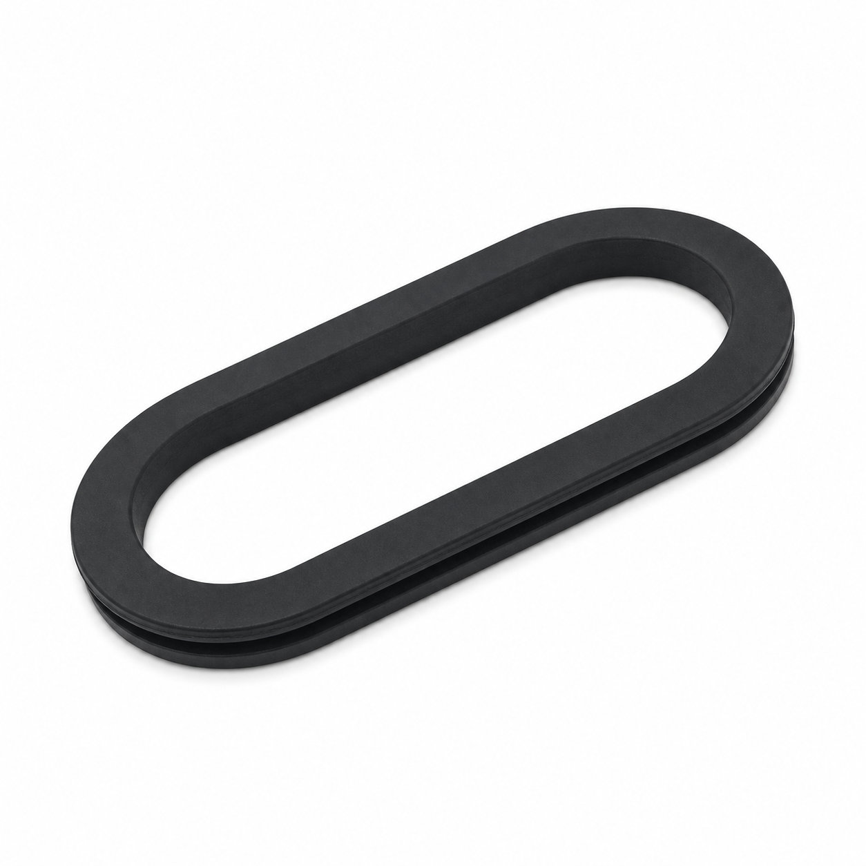
Custom manufacturing example · Silicone Rubber 30mm Oval Grommet manufacturer
CUSTOM RUBBER & SILICONE MANUFACTURING
A custom component for your assembly.
Define the mating surfaces, dimensions and working conditions. ETOL manufactures the part to the agreed design and material.
Share the part, its application and your estimated quantity.

Selected for the contact, temperature and movement
Define the visible surfaces and intended color
Develop holes, lips and walls around the mating parts
Match the attachment and installation method
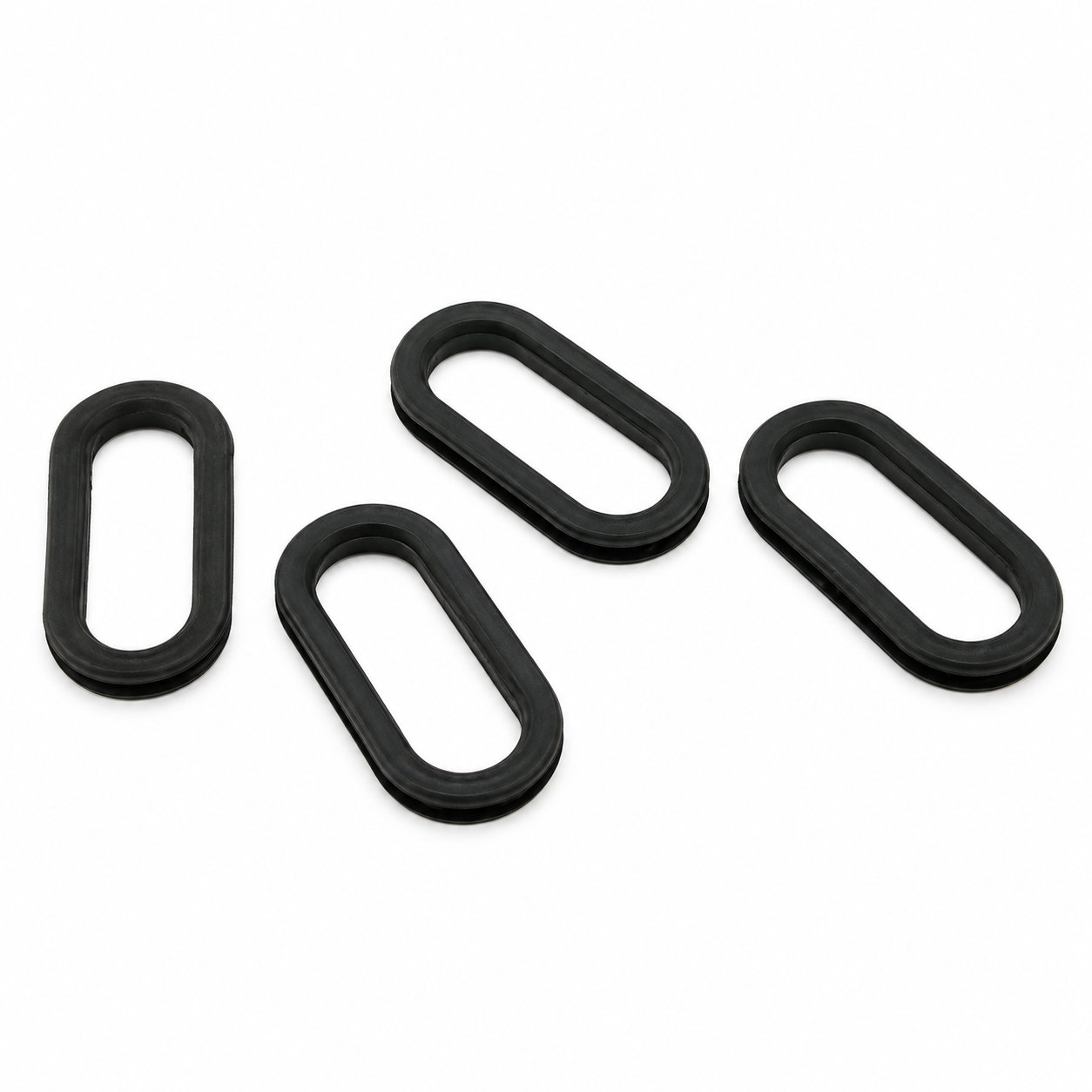
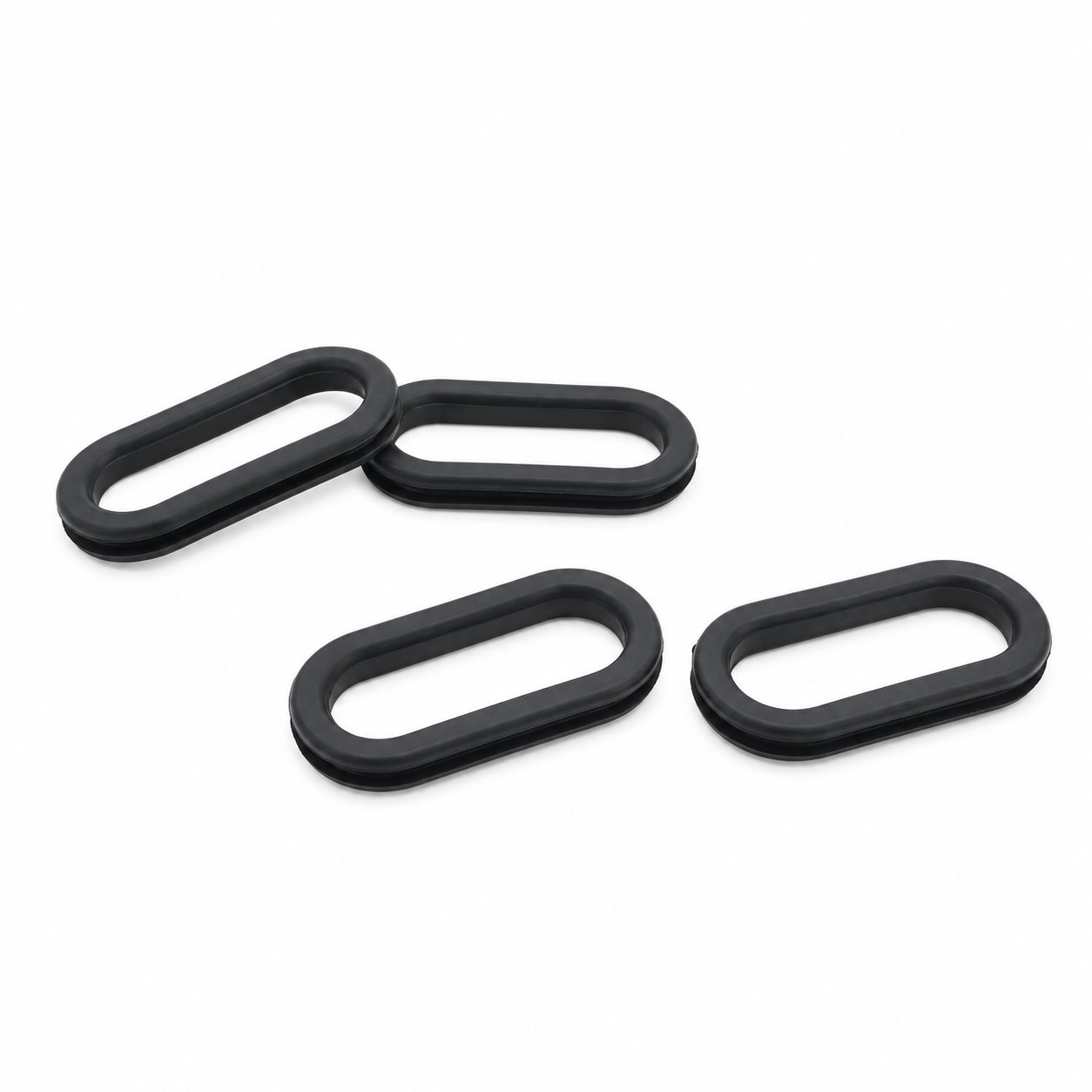
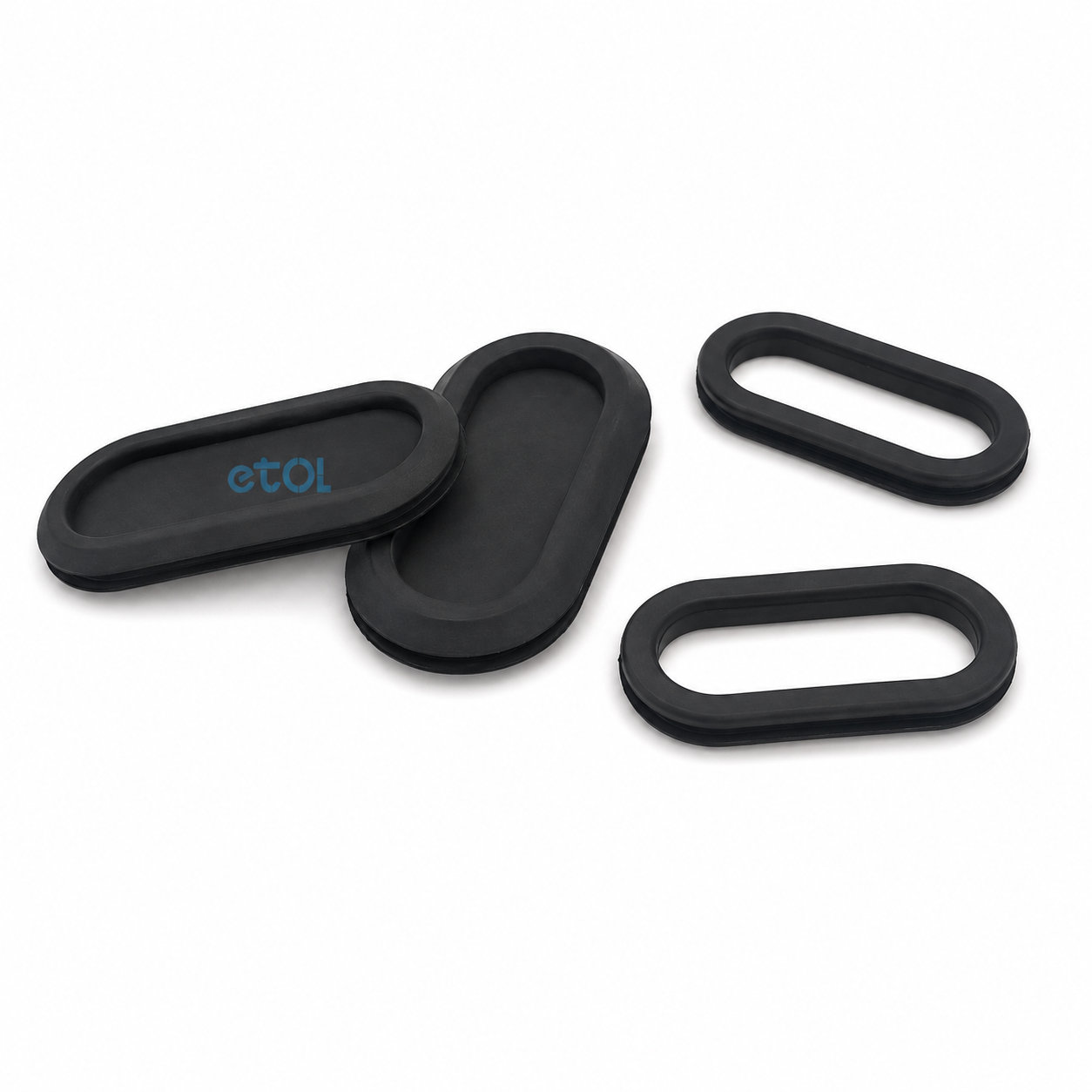
The 30mm Oval Grommet family uses a 30 mm short groove dimension with three listed lengths: 60, 75 and 90 mm. It provides a silicone rubber edge liner for elongated cable openings where the available width is fixed but the routing space can extend along the panel.
The respective inside openings are 26 by 56, 26 by 71 and 26 by 86 mm. All three retain the same internal width, so moving to a longer version creates additional length rather than extra clearance across the narrow axis. This is useful when comparing a side-by-side wire arrangement with a bundle that is too thick to fit through 26 mm.
Their outside outlines are 38 by 68, 38 by 83 and 38 by 98 mm. Allow that full footprint on the panel face, including clearance from ribs or adjacent openings. Groove widths of 1, 1.5, 2, 2.5, 3 and 4 mm are listed; select the one corresponding to the wall at the cutout.
Overall thickness also changes across the groove choices: the listed 1 mm groove version is 6 mm thick overall, while the 3 and 4 mm groove versions are both shown as 8 mm overall. This illustrates why overall height alone cannot identify the correct panel fit. Keep the groove width visible when comparing parts with a similar side profile.
Lay out the real cable arrangement before committing to the longest opening. More passage length does not remove the need for cable support or suitable bend space behind the panel. When inserting the part, settle its long edges and rounded ends fully, then inspect the narrower sides while moving the cable into its final route.
Photos illustrate structure or material only. More passage length does not remove the need for cable support or suitable bend space behind the panel. ETOL directly manufactures custom-shaped silicone and rubber parts to your requirements.
FIND THE RIGHT FIT
Choose a through-hole or blind-hole profile, then compare the dimensions for your panel and cable arrangement.
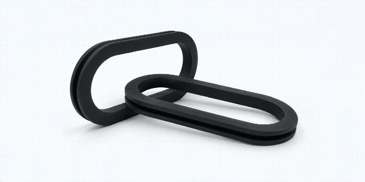
133 sizes with an open passage for cables. Match the outside dimensions, opening, panel hole, panel thickness and overall thickness. Dimensions are in millimeters (mm).

| P/N | OD | ID | GD | GW | T |
|---|---|---|---|---|---|
| OG9001 | 29×49 | 20×40 | 23×43 | 4 | 8 |
| OG9002 | 71.5×37.2 | 53.5×19.2 | 59.5×25.2 | 3.5 | 7.2 |
| OG9003 | 112×43.5 | 98.5×30 | 101.5×33 | 3.5 | 7.2 |
| OG9004 | 83×40 | 71×28 | 75×32 | 2 | 6 |
| OG9005 | 39×19 | 32×12 | 35×15 | 2 | 5 |
| OG9006 | 19.5×10 | 13.5×4 | 15.5×6 | 2 | 5 |
| OG9007 | 14×24 | 8×18 | 10×20 | 1 | 4 |
| OG9008 | 14×24 | 8×18 | 10×20 | 1.5 | 4.5 |
| OG9009 | 14×24 | 8×18 | 10×20 | 2 | 5 |
| OG9010 | 14×24 | 8×18 | 10×20 | 2.5 | 5.5 |
| OG9011 | 14×24 | 8×18 | 10×20 | 3 | 6 |
| OG9012 | 14×24 | 8×18 | 10×20 | 4 | 7 |
| OG9013 | 14×29 | 8×23 | 10×25 | 1 | 4 |
| OG9014 | 14×29 | 8×23 | 10×25 | 1.5 | 4.5 |
| OG9015 | 14×29 | 8×23 | 10×25 | 2 | 5 |
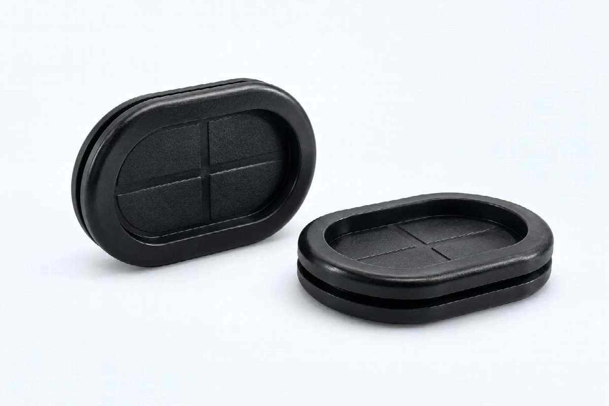
16 sizes with a closed oval profile. Compare the groove dimensions and panel thickness for the mounting fit. Dimensions are in millimeters (mm).

| P/N | OD | ID | GD | GW | T |
|---|---|---|---|---|---|
| GBH2002 | 15×30 | 10×25 | 13×27 | 3 | 10 |
| GBH2003 | 23×48 | 17×42 | 20×44 | 3 | 10 |
| GBH2004 | 25×51 | 16×42 | 20×45 | 2 | 9 |
| GBH2005 | 25×51 | 16×42 | 20×50 | 2 | 9 |
| GBH2006 | 30×45 | 21×37 | 25×40 | 2 | 9 |
| GBH2007 | 37×91 | 24×78 | 30×85 | 2 | 11 |
| GBH2008 | 46×84 | 29×67 | 37×75 | 2 | 11 |
| GBH2009 | 46×90 | 33×77 | 40×83 | 3 | 14 |
| GBH2010 | 58×83 | 45×70 | 50×75 | 3 | 14 |
| GBH2011 | 41×105 | 26×90 | 35×100 | 2.5 | 9.5 |
| GBH2013 | 38×83 | 26×71 | 30×75 | 4 | 9 |
| GBH2014 | 48×128 | 26×110 | 40×120 | 3 | 10 |
| GBH2015 | 25×40 | 16×31 | 20×35 | 1.5 | 5.5 |
| GBH2016 | 38×53.8 | 24×39.8 | 31×46.8 | 2.54 | 6.35 |
| GBH2017 | 26×66 | 17×57 | 20×60 | 1 | 5 |
Can't find the right size? Contact us for custom dimensions tailored to your requirements.
Identify key dimensions, mating surfaces and quantity
Agree the compound and manufacturing approach
Review the fit and agreed requirements in the assembly
Manufacture and check against the approved requirements
Identify temperature, contact fluids and repeated movement.
Consider hardness together with wall thickness and support.
Check access, mating dimensions and the fitting sequence.
Yes. Show the receiving opening, contact surfaces and clearance limits. We can review the dimensions and retaining features around the intended fit.
Agree the critical dimensions, material, hardness, visible surfaces and sample requirements. Explain how the part is installed and which interfaces control its function.
A sample can help explain the structure. Compare it with the assembly because wear, swelling or compression may have changed its original dimensions.
The material, part geometry, tooling, quantity and finishing affect the quotation. Include the intended batch size and delivery destination when describing your requirements.
DISCUSS THIS COMPONENT
Share the fit, operating conditions and quantity with our manufacturing team.
EXPLORE RELATED DESIGNS
Explore similar part structures and applications for your next project.