Working conditions
Identify temperature, contact fluids and repeated movement.

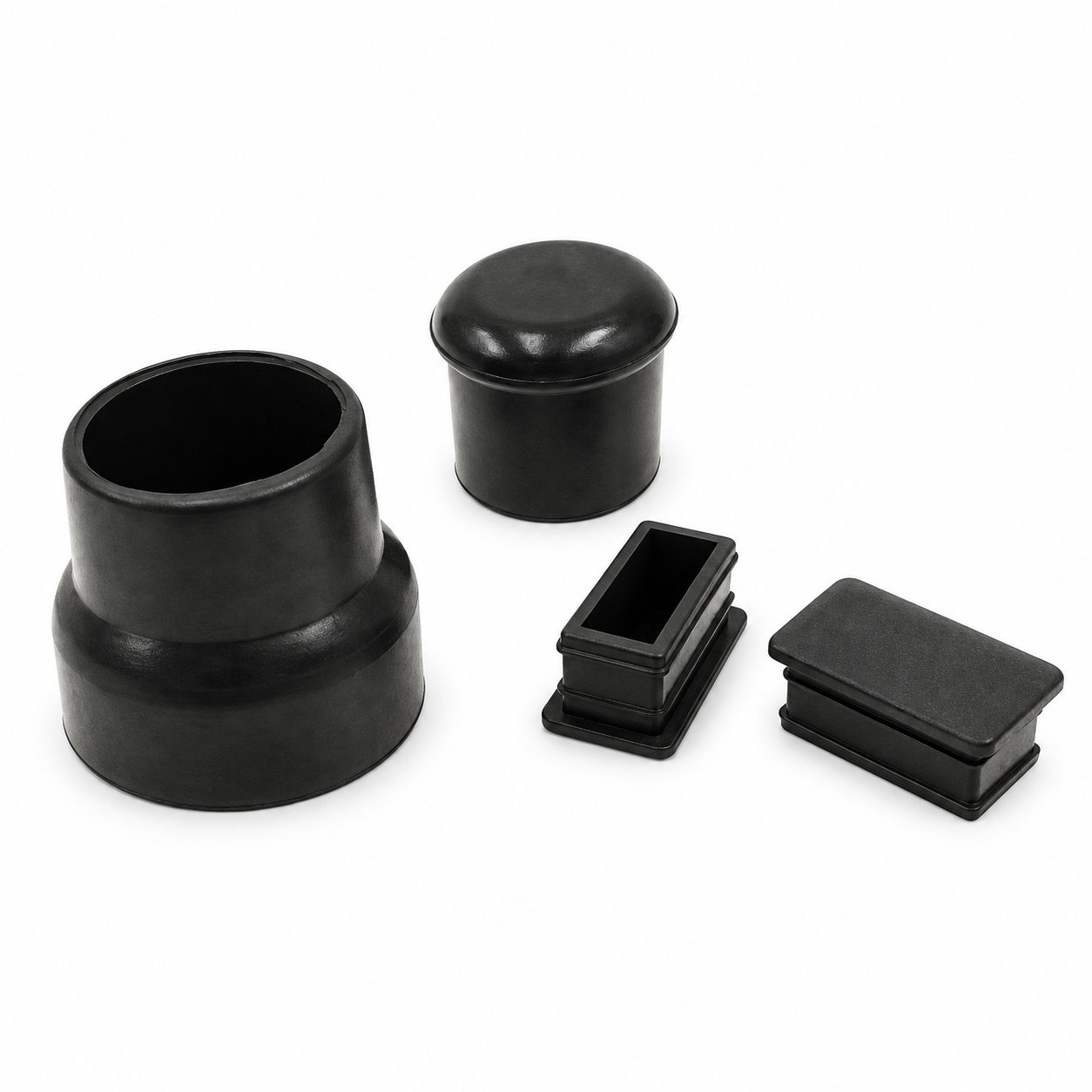
Custom manufacturing example · Custom molded anti-slip ladder rubber foot protector
CUSTOM RUBBER & SILICONE MANUFACTURING
A custom component for your assembly.
Define the mating surfaces, dimensions and working conditions. ETOL manufactures the part to the agreed design and material.
Share the part, its application and your estimated quantity.

Selected for the contact, temperature and movement
Define the visible surfaces and intended color
Develop holes, lips and walls around the mating parts
Match the attachment and installation method
A ladder rubber foot protector forms the contact between a compatible ladder support and the ground. Its custom profile should follow the leg end and the stance specified for that ladder. A component that fits a tube is not automatically suitable for the complete support arrangement.
Check the base orientation with the ladder positioned for its intended use. The receiving cavity must let the leg reach its seat while the contact face meets the supporting surface appropriately. A partly seated tip can change the effective support height and the way the load reaches the rubber.
Select the formulation and dimensions for the specific ladder design, including its retention features and required contact conditions. Do not substitute an ordinary furniture cap based only on appearance. During inspection, keep the underside free of particles and look for wear that exposes the underlying member. Examine the rim for loosening or splitting. A damaged foot should be replaced with the compatible version rather than trimmed or packed to make it sit differently, preserving the original ladder support geometry.
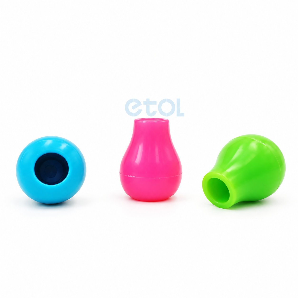
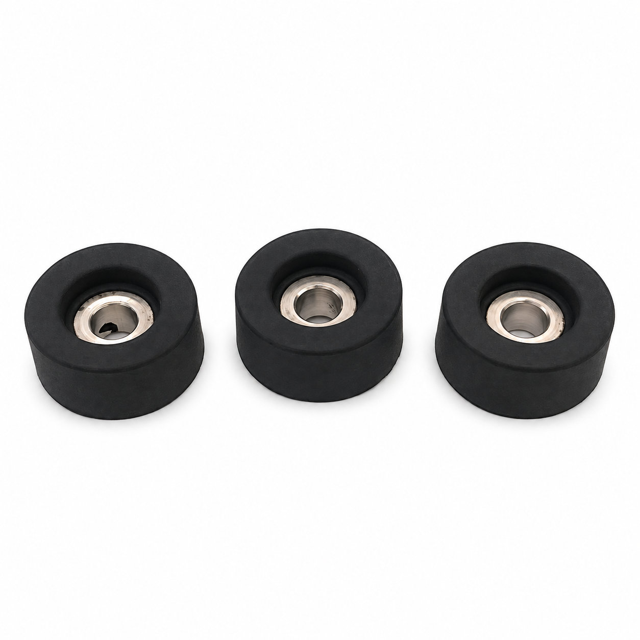
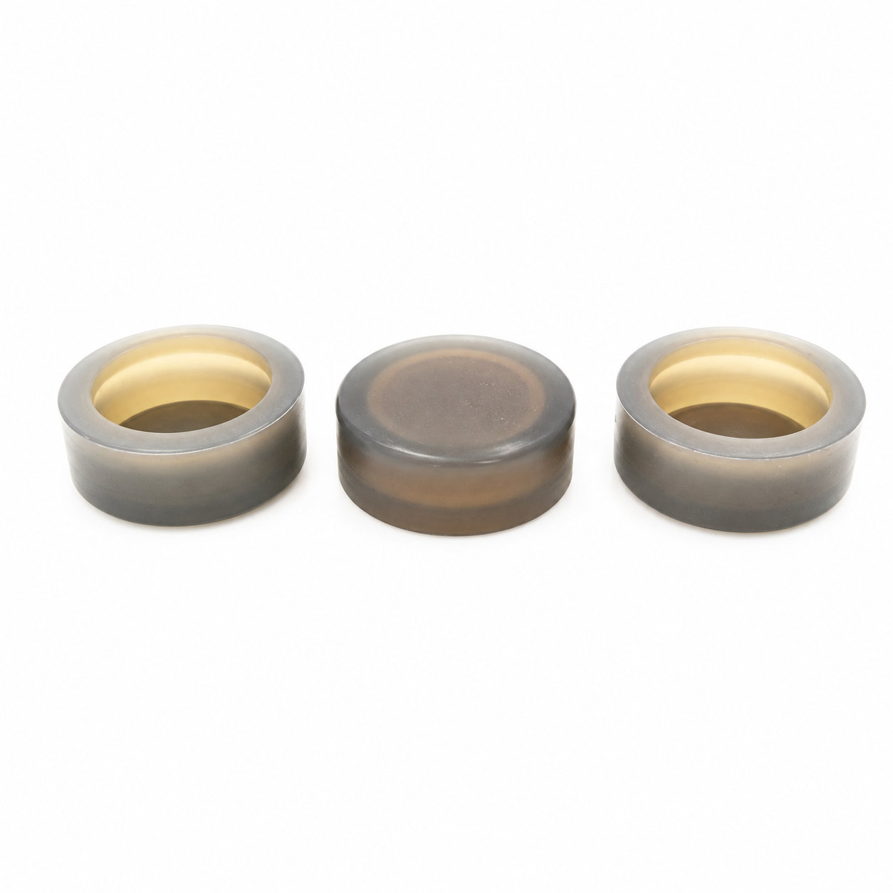
Photos illustrate structure or material appearance only. The receiving cavity must let the leg reach its seat while the contact face meets the supporting surface appropriately. ETOL directly manufactures custom-shaped silicone and rubber parts to your requirements.
FIND THE RIGHT FIT
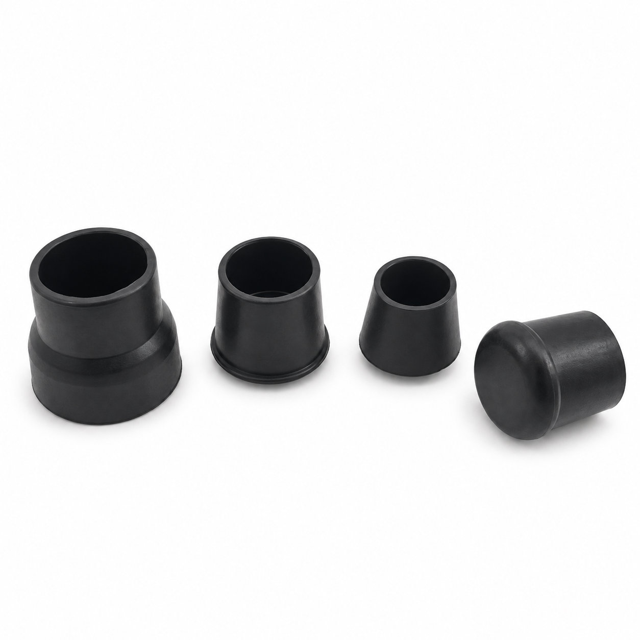
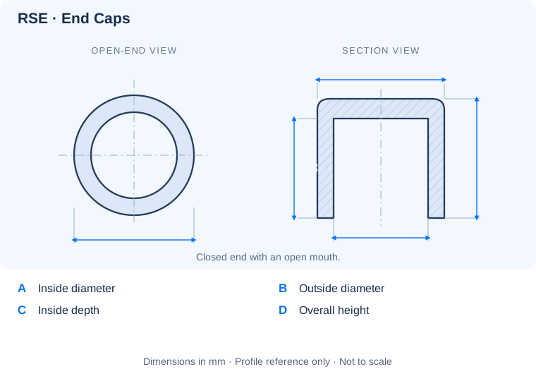
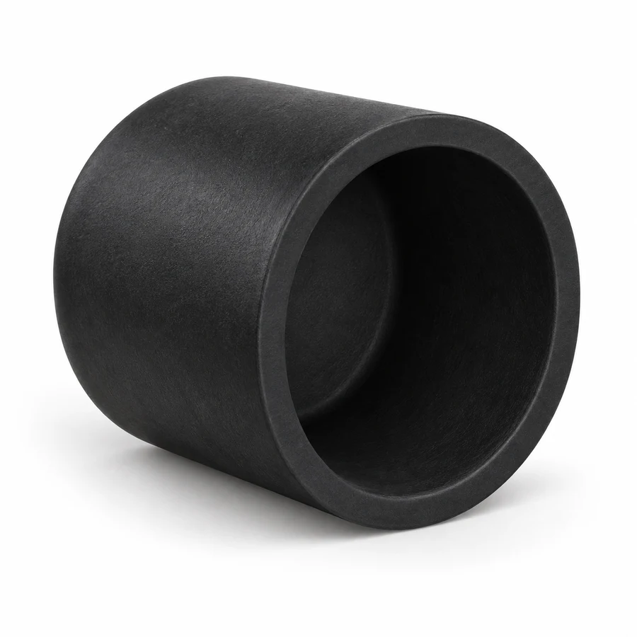
Compare inside diameter A with the outside of the part being covered. Check inside depth C and overall dimensions B and D for available clearance. These RSE references show a round cap with one closed end.
43 closed-end cap sizes. A is the inside diameter and C is the usable internal depth; B and D describe the outside envelope.
| P/N | A | B | C | D | Color | Unit |
|---|---|---|---|---|---|---|
| RSE3.7-7-9 | 3.7 | 7 | 9 | 11 | black,white | mm |
| RSE4.7-8-9 | 4.7 | 8 | 9 | 11 | black,white | mm |
| RSE5.7-9-10 | 5.7 | 9 | 10 | 12 | black,white | mm |
| RSE6.7-10-10 | 6.7 | 10 | 10 | 12 | black,white | mm |
| RSE7.7-11-11 | 7.7 | 11 | 11 | 13 | black,white | mm |
| RSE8.7-12-12 | 8.7 | 12 | 12 | 14 | black,white | mm |
| RSE9.7-14-13 | 9.7 | 14 | 13 | 15 | black,white | mm |
| RSE10.7-15-14 | 10.7 | 15 | 14 | 16 | black,white | mm |
| RSE11.7-16-15 | 11.7 | 16 | 15 | 17 | black,white | mm |
| RSE12.7-17-15 | 12.7 | 17 | 15 | 18 | black,white | mm |
| RSE13.7-18-15 | 13.7 | 18 | 15 | 18 | black,white | mm |
| RSE14.7-19-15 | 14.7 | 19 | 15 | 18 | black,white | mm |
| RSE15.7-20-16 | 15.7 | 20 | 16 | 19 | black,white | mm |
| RSE16.7-21-16 | 16.7 | 21 | 16 | 19 | black,white | mm |
| RSE17.7-22-16 | 17.7 | 22 | 16 | 19 | black,white | mm |
Need a different fit? Share the opening dimensions, mating profile and intended use for a custom size.
Identify key dimensions, mating surfaces and quantity
Agree the compound and manufacturing approach
Review the fit and agreed requirements in the assembly
Manufacture and check against the approved requirements
Identify temperature, contact fluids and repeated movement.
Consider hardness together with wall thickness and support.
Check access, mating dimensions and the fitting sequence.
Yes. Show the receiving opening, contact surfaces and clearance limits. We can review the dimensions and retaining features around the intended fit.
Agree the critical dimensions, material, hardness, visible surfaces and sample requirements. Explain how the part is installed and which interfaces control its function.
A sample can help explain the structure. Compare it with the assembly because wear, swelling or compression may have changed its original dimensions.
The material, part geometry, tooling, quantity and finishing affect the quotation. Include the intended batch size and delivery destination when describing your requirements.
DISCUSS THIS COMPONENT
Share the fit, operating conditions and quantity with our manufacturing team.
EXPLORE RELATED DESIGNS
Explore similar part structures and applications for your next project.