Working conditions
Identify temperature, contact fluids and repeated movement.

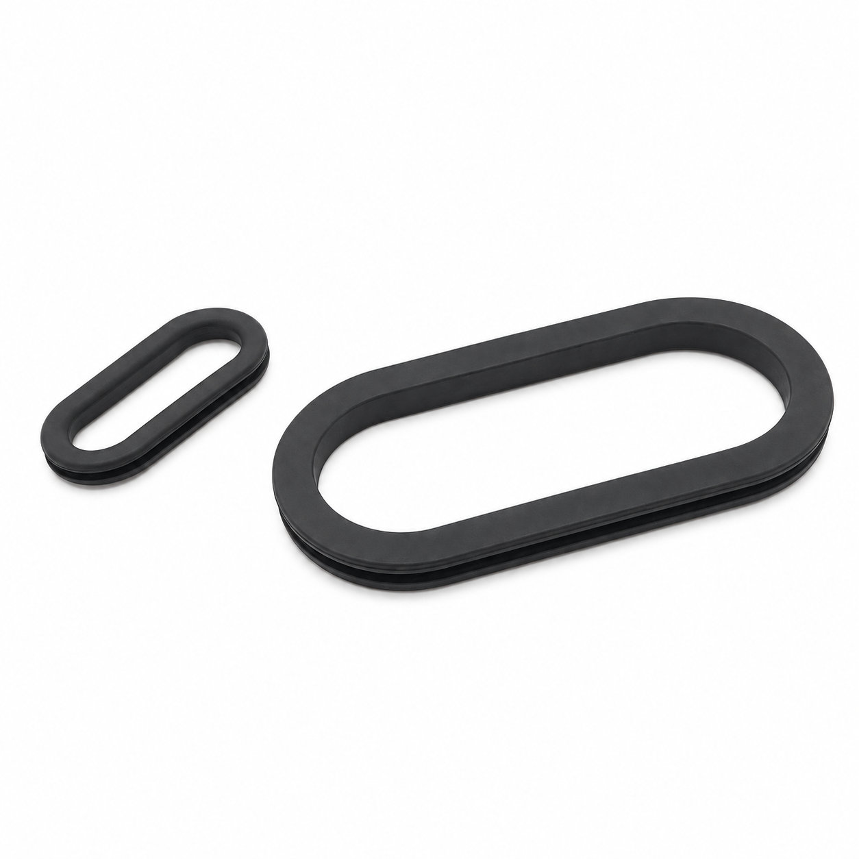
Custom manufacturing example · Oval cable wire grommet seals professional manufacturer
CUSTOM RUBBER & SILICONE MANUFACTURING
A custom component for your assembly.
Define the mating surfaces, dimensions and working conditions. ETOL manufactures the part to the agreed design and material.
Share the part, its application and your estimated quantity.

Selected for the contact, temperature and movement
Define the visible surfaces and intended color
Develop holes, lips and walls around the mating parts
Match the attachment and installation method
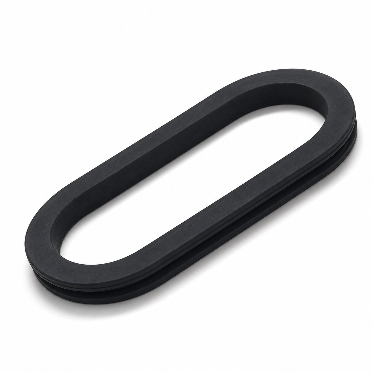
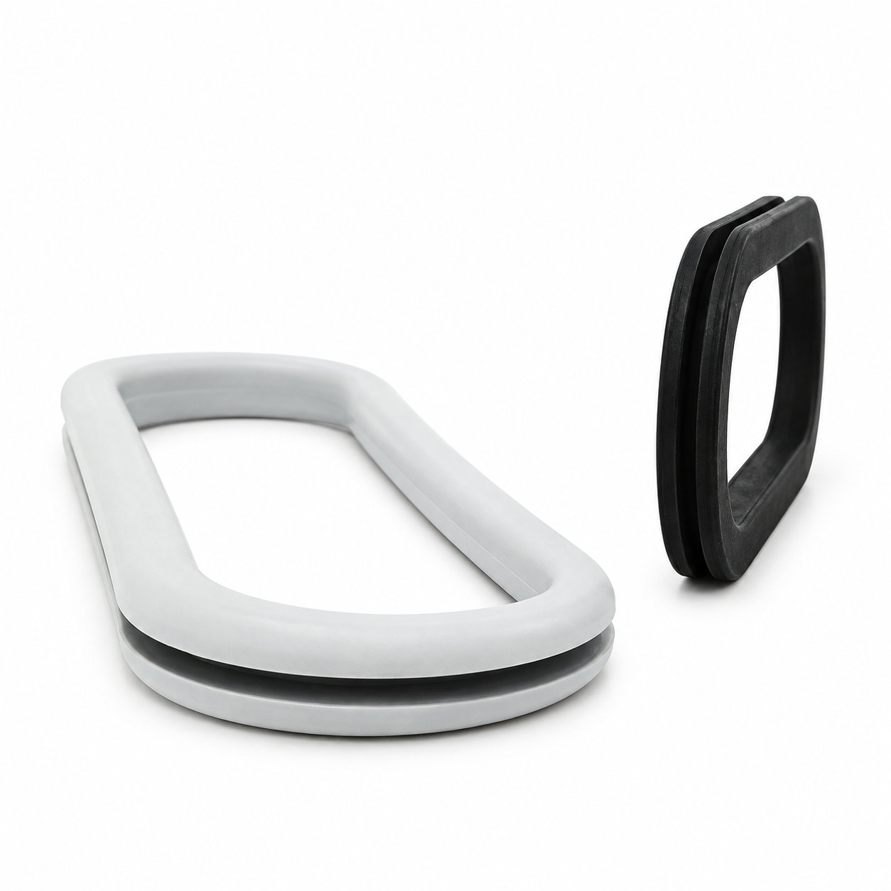
An oval cable wire grommet gives a wider cable passage than a round profile of comparable short-axis size. It covers the perimeter of the panel opening while leaving the center available for wiring. This page's dimension tables distinguish the groove, outside flange, inside opening, overall thickness and groove width, allowing the selection to start from the enclosure rather than the product photograph.
Use the groove dimensions to identify the matching cutout profile, then check the groove width against the panel thickness. The outside dimensions describe the flange envelope, not the hole to cut. The inside dimensions describe the remaining passage after the rubber occupies the edge. Confusing these measurements can produce a part that appears correctly sized but leaves too little room for the cable bundle.
For example, the catalog's 10 by 20 entries share outside dimensions of 14 by 24 and an inside opening of 8 by 18, but offer different groove widths and overall thicknesses. Choosing the same oval outline does not therefore complete the selection. Larger entries also need to be checked individually rather than assuming a fixed difference between the groove and flange dimensions throughout the table.
Before ordering, compare the selected entry with the enclosure drawing and the largest connector that must pass through during assembly. Check available flange space on the hidden side of the panel, where ribs or hardware may be close to the cutout. A custom profile can address an enclosure that needs a different groove outline, flange envelope or panel thickness.
Seat the groove around the entire opening and inspect both curved ends after routing. Do not enlarge the panel from a flange measurement or force a bundle through by stretching the grommet out of position. Keep the selected table entry with the purchasing drawing to make repeat orders unambiguous.
Photos illustrate structure or material only. A custom profile can address an enclosure that needs a different groove outline, flange envelope or panel thickness. ETOL directly manufactures custom-shaped silicone and rubber parts to your requirements.
FIND THE RIGHT FIT
Choose a through-hole or blind-hole profile, then compare the dimensions for your panel and cable arrangement.
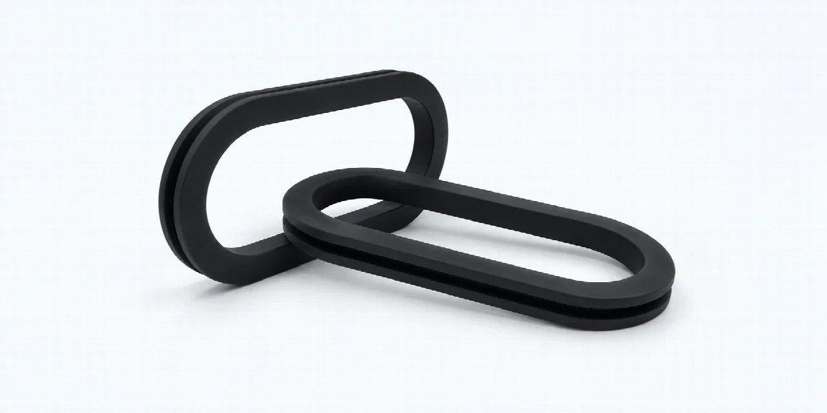
133 sizes with an open passage for cables. Match the outside dimensions, opening, panel hole, panel thickness and overall thickness. Dimensions are in millimeters (mm).

| P/N | OD | ID | GD | GW | T |
|---|---|---|---|---|---|
| OG9001 | 29×49 | 20×40 | 23×43 | 4 | 8 |
| OG9002 | 71.5×37.2 | 53.5×19.2 | 59.5×25.2 | 3.5 | 7.2 |
| OG9003 | 112×43.5 | 98.5×30 | 101.5×33 | 3.5 | 7.2 |
| OG9004 | 83×40 | 71×28 | 75×32 | 2 | 6 |
| OG9005 | 39×19 | 32×12 | 35×15 | 2 | 5 |
| OG9006 | 19.5×10 | 13.5×4 | 15.5×6 | 2 | 5 |
| OG9007 | 14×24 | 8×18 | 10×20 | 1 | 4 |
| OG9008 | 14×24 | 8×18 | 10×20 | 1.5 | 4.5 |
| OG9009 | 14×24 | 8×18 | 10×20 | 2 | 5 |
| OG9010 | 14×24 | 8×18 | 10×20 | 2.5 | 5.5 |
| OG9011 | 14×24 | 8×18 | 10×20 | 3 | 6 |
| OG9012 | 14×24 | 8×18 | 10×20 | 4 | 7 |
| OG9013 | 14×29 | 8×23 | 10×25 | 1 | 4 |
| OG9014 | 14×29 | 8×23 | 10×25 | 1.5 | 4.5 |
| OG9015 | 14×29 | 8×23 | 10×25 | 2 | 5 |
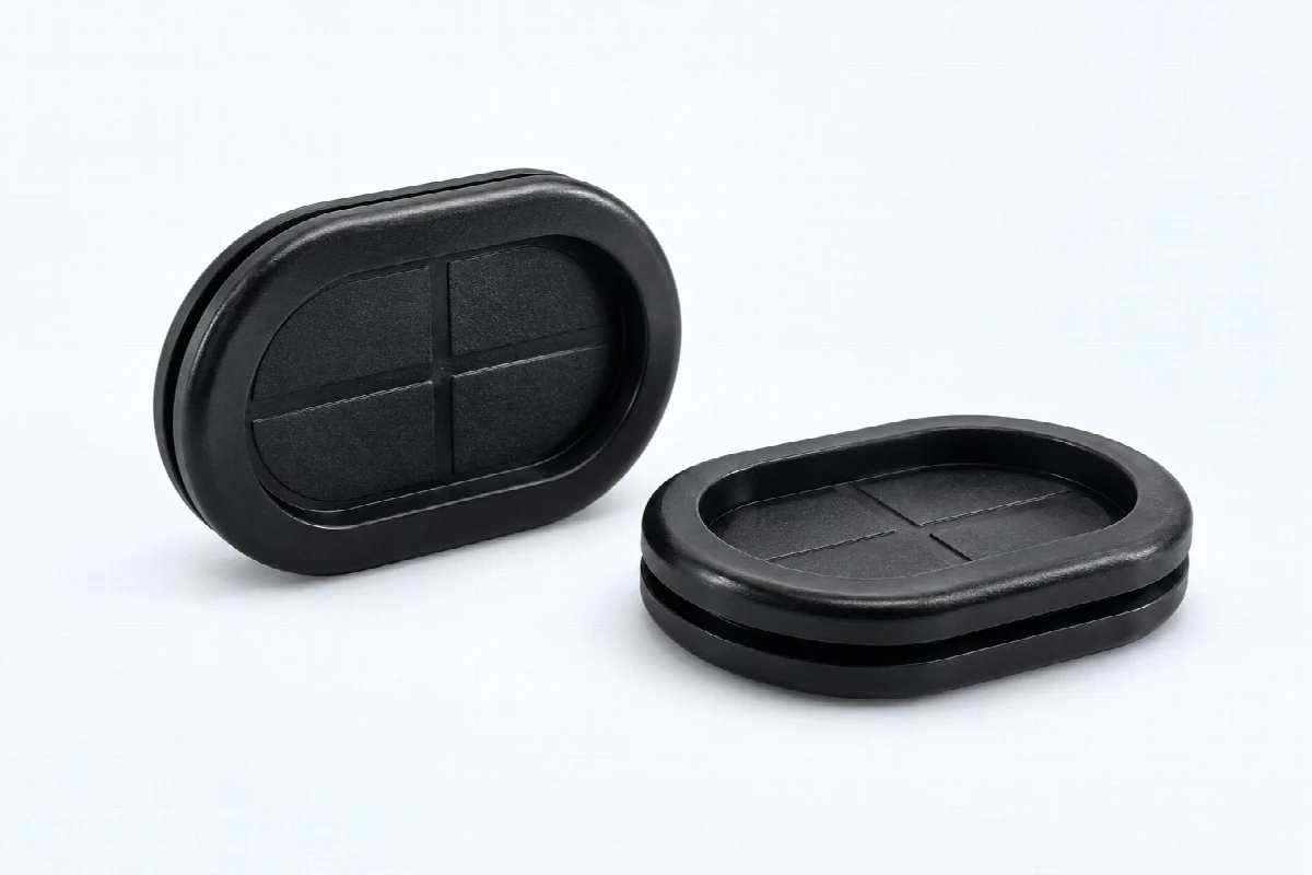
16 sizes with a closed oval profile. Compare the groove dimensions and panel thickness for the mounting fit. Dimensions are in millimeters (mm).

| P/N | OD | ID | GD | GW | T |
|---|---|---|---|---|---|
| GBH2002 | 15×30 | 10×25 | 13×27 | 3 | 10 |
| GBH2003 | 23×48 | 17×42 | 20×44 | 3 | 10 |
| GBH2004 | 25×51 | 16×42 | 20×45 | 2 | 9 |
| GBH2005 | 25×51 | 16×42 | 20×50 | 2 | 9 |
| GBH2006 | 30×45 | 21×37 | 25×40 | 2 | 9 |
| GBH2007 | 37×91 | 24×78 | 30×85 | 2 | 11 |
| GBH2008 | 46×84 | 29×67 | 37×75 | 2 | 11 |
| GBH2009 | 46×90 | 33×77 | 40×83 | 3 | 14 |
| GBH2010 | 58×83 | 45×70 | 50×75 | 3 | 14 |
| GBH2011 | 41×105 | 26×90 | 35×100 | 2.5 | 9.5 |
| GBH2013 | 38×83 | 26×71 | 30×75 | 4 | 9 |
| GBH2014 | 48×128 | 26×110 | 40×120 | 3 | 10 |
| GBH2015 | 25×40 | 16×31 | 20×35 | 1.5 | 5.5 |
| GBH2016 | 38×53.8 | 24×39.8 | 31×46.8 | 2.54 | 6.35 |
| GBH2017 | 26×66 | 17×57 | 20×60 | 1 | 5 |
Can't find the right size? Contact us for custom dimensions tailored to your requirements.
Identify key dimensions, mating surfaces and quantity
Agree the compound and manufacturing approach
Review the fit and agreed requirements in the assembly
Manufacture and check against the approved requirements
Identify temperature, contact fluids and repeated movement.
Consider hardness together with wall thickness and support.
Check access, mating dimensions and the fitting sequence.
Yes. Show the receiving opening, contact surfaces and clearance limits. We can review the dimensions and retaining features around the intended fit.
Agree the critical dimensions, material, hardness, visible surfaces and sample requirements. Explain how the part is installed and which interfaces control its function.
A sample can help explain the structure. Compare it with the assembly because wear, swelling or compression may have changed its original dimensions.
The material, part geometry, tooling, quantity and finishing affect the quotation. Include the intended batch size and delivery destination when describing your requirements.
DISCUSS THIS COMPONENT
Share the fit, operating conditions and quantity with our manufacturing team.
EXPLORE RELATED DESIGNS
Explore similar part structures and applications for your next project.