Working conditions
Identify temperature, contact fluids and repeated movement.

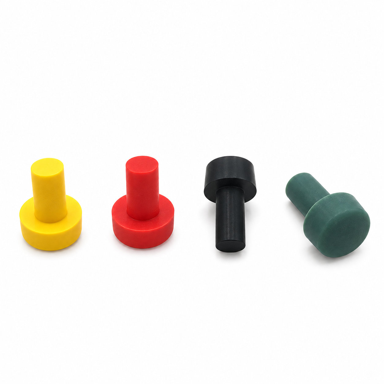
Custom manufacturing example · T shaped silicone rubber stopper manufacturer
CUSTOM RUBBER & SILICONE MANUFACTURING
A custom component for your assembly.
Define the mating surfaces, dimensions and working conditions. ETOL manufactures the part to the agreed design and material.
Share the part, its application and your estimated quantity.

Selected for the contact, temperature and movement
Define the visible surfaces and intended color
Develop holes, lips and walls around the mating parts
Match the attachment and installation method
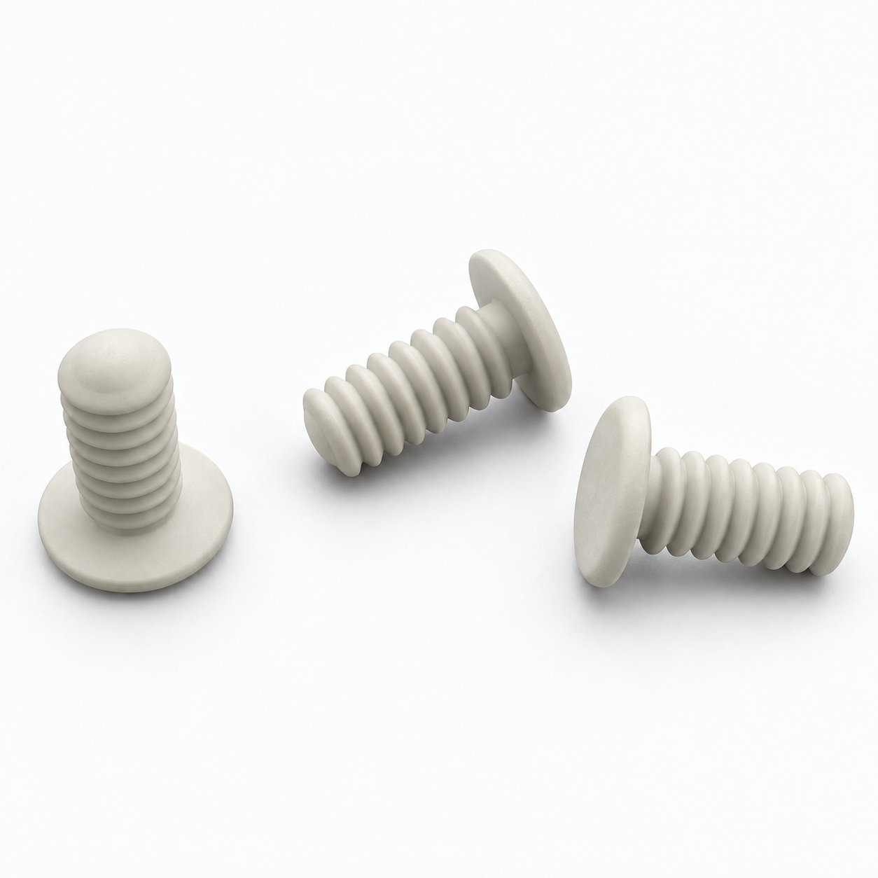
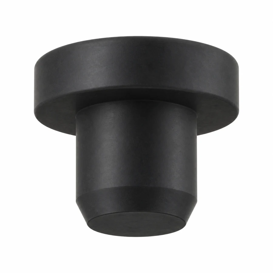
A T shaped silicone rubber stopper has a wider head above a narrower insertion section. The head provides a visible seating reference and an accessible surface for removal, while the stem fits the opening being covered. This form is useful where the plug should remain reachable instead of disappearing into the bore.
Check the space above and beside the opening before choosing the head diameter. A broad top needs clearance from nearby walls, covers and controls. The stem length should suit the usable bore depth so it does not bottom out before the head reaches its intended position.
ETOL can customize the head, stem, material, hardness and color. If the opening is accessed regularly, try the sample using the intended removal method; a head that is easy to see may still be difficult to grip in a recessed location.
Insert the stopper straight into a clean opening and avoid levering under its head with a sharp tool. Inspect the junction between head and stem after repeated removal, and replace a plug that has torn or no longer seats evenly. Confirm sealing requirements with the actual mating component rather than judging the fit only from the head resting on the surface.
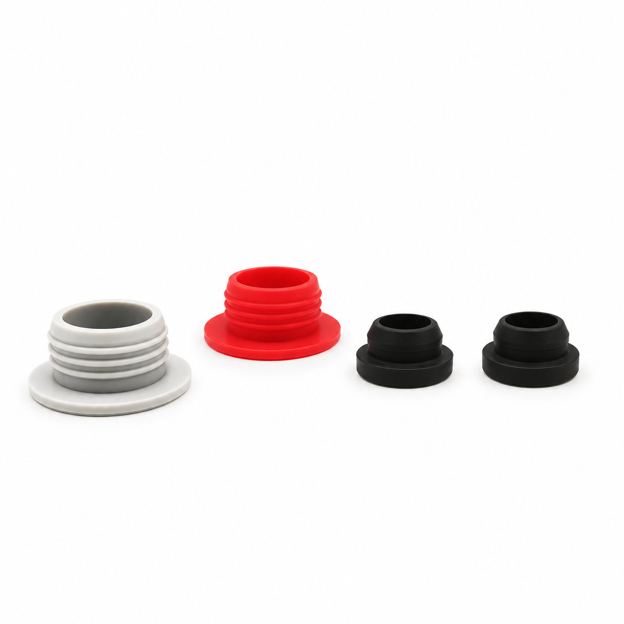
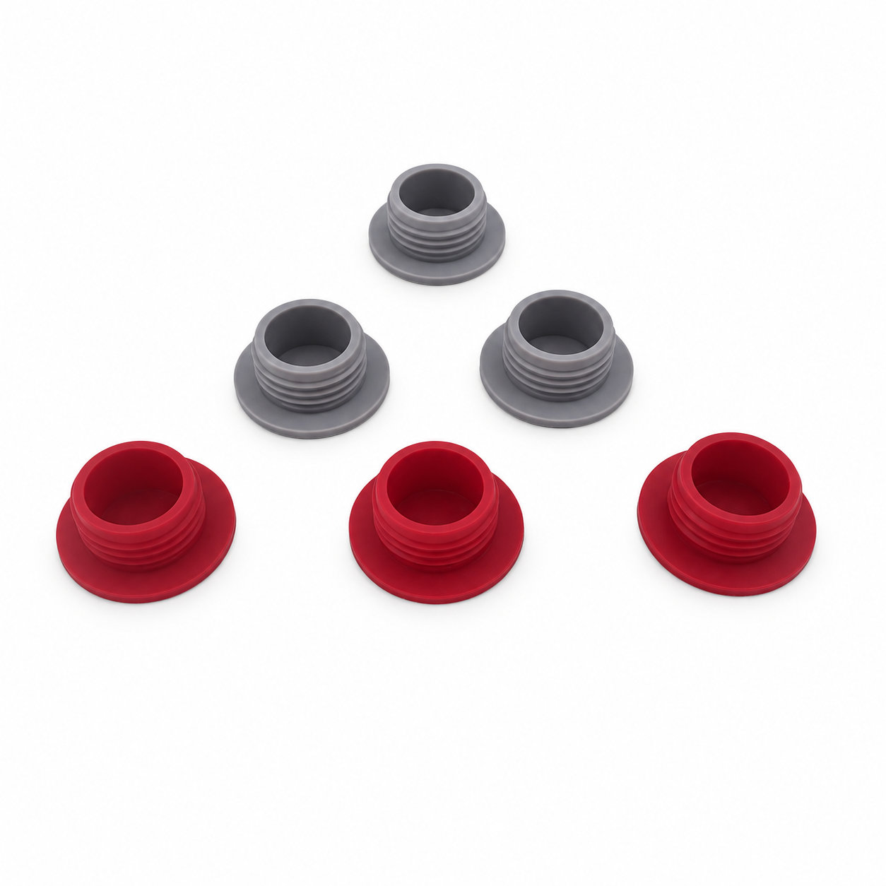
Photos illustrate structure or material appearance only. The stem length should suit the usable bore depth so it does not bottom out before the head reaches its intended position. ETOL directly manufactures custom-shaped silicone and rubber parts to your requirements.
FIND THE RIGHT FIT
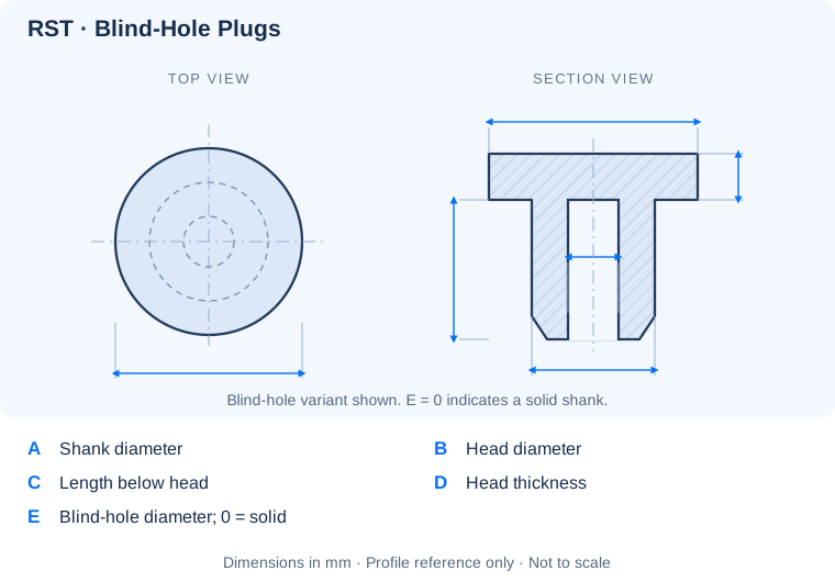
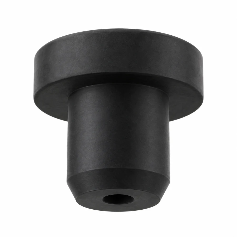
Choose a blind-hole, tapered, undercut or solid T-shaped profile, then compare its dimensions with the opening and available seating depth. Each profile has its own drawing and dimension meanings.
155 T-shaped plug sizes. Match shank diameter A, head diameter B, shank length C and head thickness D. E is the bottom blind-hole diameter; E = 0 indicates a solid shank.
| P/N | A | B | C | D | E | Unit |
|---|---|---|---|---|---|---|
| RST2.5-5.5-5.3 | 2.5 | 5.5 | 5.3 | 2 | 0 | mm |
| RST2.7-5.5-5 | 2.7 | 5.5 | 5 | 2 | 0 | mm |
| RST3-4.3-4.5 | 3 | 4.3 | 4.5 | 0.8 | 0 | mm |
| RST3-7-7 | 3 | 7 | 7 | 2.2 | 0 | mm |
| RST3.3-6.5-6 | 3.3 | 6.5 | 6 | 1.5 | 0 | mm |
| RST3.5-6.5-6 | 3.5 | 6.5 | 6 | 2 | 0 | mm |
| RST3.8-7-10.5 | 3.8 | 7 | 10.5 | 1.5 | 0 | mm |
| RST3.8-7-7 | 3.8 | 7 | 7 | 1.5 | 0 | mm |
| RST3.8-7-6 | 3.8 | 7 | 6 | 1.5 | 0 | mm |
| RST4-7.5-6 | 4 | 7.5 | 6 | 2 | 0 | mm |
| RST4-9.5-7 | 4 | 9.5 | 7 | 2.5 | 0 | mm |
| RST4.3-8-6 | 4.3 | 8 | 6 | 1.5 | 0 | mm |
| RST4.5-7.5-6 | 4.5 | 7.5 | 6 | 2 | 0 | mm |
| RST4.8-6.8-3.6 | 4.8 | 6.8 | 3.6 | 0.9 | 0 | mm |
| RST4.8-9-7 | 4.8 | 9 | 7 | 1.5 | 0 | mm |
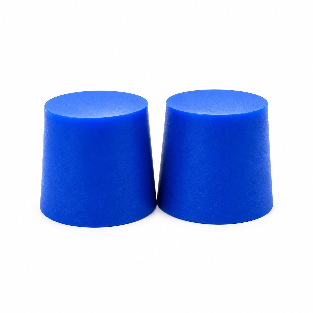
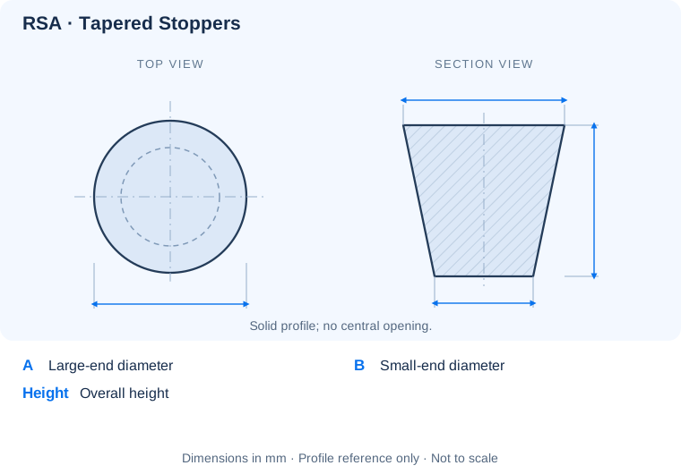
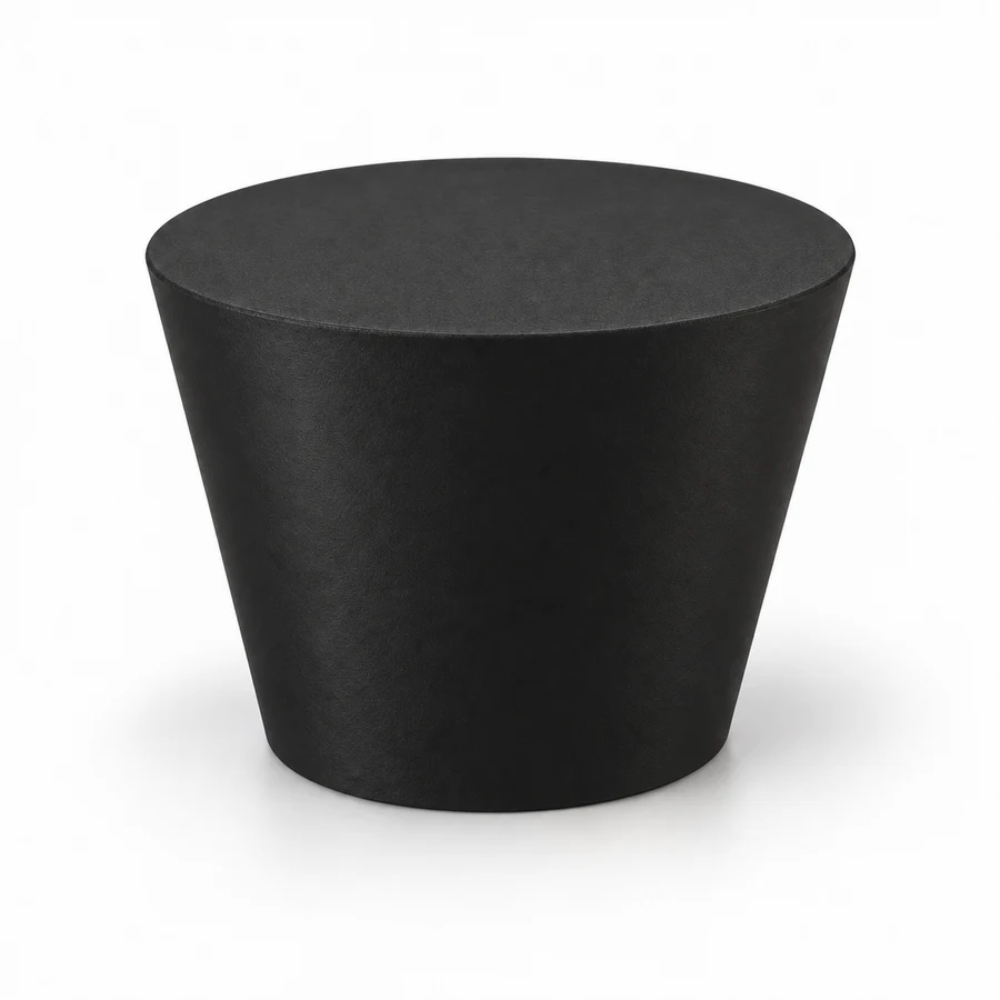
70 tapered stopper sizes. Compare the large-end diameter A, small-end diameter B and overall height with the opening and intended insertion depth.
| P/N | A | B | Height | Color | Material | Unit |
|---|---|---|---|---|---|---|
| RSA1.6-0.4-15.9 | 1.6 | 0.4 | 15.9 | Transparent | Silicone | mm |
| RSA2-0.5-19.1 | 2 | 0.5 | 19.1 | Transparent | Silicone | mm |
| RSA3.2-0.8-15.9 | 3.2 | 0.8 | 15.9 | Transparent | Silicone | mm |
| RSA3.2-1.6-15.9 | 3.2 | 1.6 | 15.9 | Transparent | Silicone | mm |
| RSA4.8-1.6-15.9 | 4.8 | 1.6 | 15.9 | Transparent | Silicone | mm |
| RSA4.8-1.6-19.1 | 4.8 | 1.6 | 19.1 | Transparent | Silicone | mm |
| RSA5.5-1.2-38.1 | 5.5 | 1.2 | 38.1 | Transparent | Silicone | mm |
| RSA6.4-3.2-19.1 | 6.4 | 3.2 | 19.1 | Transparent | Silicone | mm |
| RSA6.4-3.2-25.4 | 6.4 | 3.2 | 25.4 | Transparent | Silicone | mm |
| RSA8.7-4.8-15.9 | 8.7 | 4.8 | 15.9 | Transparent | Silicone | mm |
| RSA8.7-4.8-25.4 | 8.7 | 4.8 | 25.4 | Transparent | Silicone | mm |
| RSA9.2-6.2-12.8 | 9.2 | 6.2 | 12.8 | Transparent | Silicone | mm |
| RSA9.5-6.5-18.5 | 9.5 | 6.5 | 18.5 | Transparent | Silicone | mm |
| RSA11-8.5-17.5 | 11 | 8.5 | 17.5 | Transparent | Silicone | mm |
| RSA11.5-6.5-25 | 11.5 | 6.5 | 25 | Transparent | Silicone | mm |
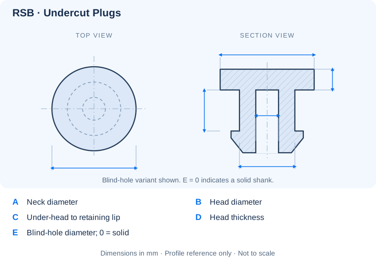
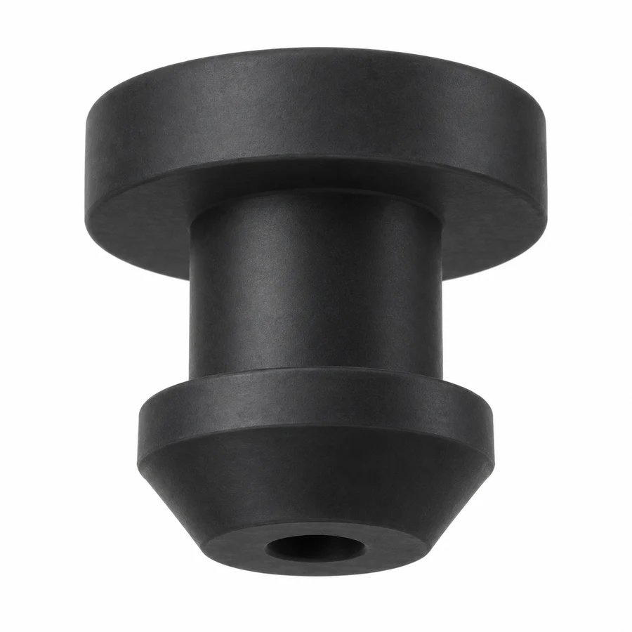
50 undercut plug sizes with a retaining lip. A is the neck diameter and C is the distance from the underside of the head to the upper face of the lip. E = 0 indicates a solid shank.
| P/N | A | B | C | D | E | Unit |
|---|---|---|---|---|---|---|
| RSB2.5-6-3 | 2.5 | 6 | 3 | 1.5 | 0 | mm |
| RSB3-7-3 | 3 | 7 | 3 | 2 | 0 | mm |
| RSB3.5-7.5-3 | 3.5 | 7.5 | 3 | 2 | 0 | mm |
| RSB3.6-7.5-6 | 3.6 | 7.5 | 6 | 2 | 0 | mm |
| RSB4-8-3 | 4 | 8 | 3 | 2 | 0 | mm |
| RSB4.5-8.5-3 | 4.5 | 8.5 | 3 | 2 | 2 | mm |
| RSB5-9-3 | 5 | 9 | 3 | 2 | 2.5 | mm |
| RSB5.5-9.5-3 | 5.5 | 9.5 | 3 | 2 | 3 | mm |
| RSB6-10-4 | 6 | 10 | 4 | 2 | 3.5 | mm |
| RSB6.5-10.5-4 | 6.5 | 10.5 | 4 | 2 | 4 | mm |
| RSB6.5-12-8 | 6.5 | 12 | 8 | 2 | 0 | mm |
| RSB6.7-8.7-5.3 | 6.7 | 8.7 | 5.3 | 1.3 | 4.1 | mm |
| RSB7-11-4 | 7 | 11 | 4 | 2 | 4.5 | mm |
| RSB7.5-11.5-4 | 7.5 | 11.5 | 4 | 2 | 5 | mm |
| RSB8-12-4 | 8 | 12 | 4 | 2 | 5.5 | mm |
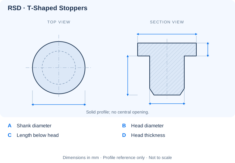
30 solid T-shaped stopper sizes. Compare shank diameter A and length C with the opening; head diameter B and thickness D define the top flange.
| P/N | A | B | C | D | Color | Material | Unit |
|---|---|---|---|---|---|---|---|
| RSD2.7-5.5-5 | 2.7 | 5.5 | 5 | 2 | Black, White | Silicone | mm |
| RSD3-7-7 | 3 | 7 | 7 | 2.2 | Black, White | Silicone | mm |
| RSD3.3-6.5-6 | 3.3 | 6.5 | 6 | 1.5 | Black, White | Silicone | mm |
| RSD3.5-6.5-6 | 3.5 | 6.5 | 6 | 2 | Black, White | Silicone | mm |
| RSD3.8-7-6 | 3.8 | 7 | 6 | 1.5 | Black, White | Silicone | mm |
| RSD4-9.5-7 | 4 | 9.5 | 7 | 2.5 | Black, White | Silicone | mm |
| RSD4.3-8-6 | 4.3 | 8 | 6 | 1.5 | Black, White | Silicone | mm |
| RSD4.5-7.5-6 | 4.5 | 7.5 | 6 | 2 | Black, White | Silicone | mm |
| RSD4.8-9-7 | 4.8 | 9 | 7 | 1.5 | Black, White | Silicone | mm |
| RSD5-12-8 | 5 | 12 | 8 | 2.8 | Black, White | Silicone | mm |
| RSD5.3-9.5-7 | 5.3 | 9.5 | 7 | 1.5 | Black, White | Silicone | mm |
| RSD5.5-8.5-7 | 5.5 | 8.5 | 7 | 2 | Black, White | Silicone | mm |
| RSD5.8-10-8 | 5.8 | 10 | 8 | 2 | Black, White | Silicone | mm |
| RSD6-13-8 | 6 | 13 | 8 | 3.5 | Black, White | Silicone | mm |
| RSD6.3-10.5-8 | 6.3 | 10.5 | 8 | 2 | Black, White | Silicone | mm |
Need a different fit? Share the opening dimensions, mating profile and intended use for a custom size.
Identify key dimensions, mating surfaces and quantity
Agree the compound and manufacturing approach
Review the fit and agreed requirements in the assembly
Manufacture and check against the approved requirements
Identify temperature, contact fluids and repeated movement.
Consider hardness together with wall thickness and support.
Check access, mating dimensions and the fitting sequence.
Yes. Show the receiving opening, contact surfaces and clearance limits. We can review the dimensions and retaining features around the intended fit.
Agree the critical dimensions, material, hardness, visible surfaces and sample requirements. Explain how the part is installed and which interfaces control its function.
A sample can help explain the structure. Compare it with the assembly because wear, swelling or compression may have changed its original dimensions.
The material, part geometry, tooling, quantity and finishing affect the quotation. Include the intended batch size and delivery destination when describing your requirements.
DISCUSS THIS COMPONENT
Share the fit, operating conditions and quantity with our manufacturing team.
EXPLORE RELATED DESIGNS
Explore similar part structures and applications for your next project.