Working conditions
Identify temperature, contact fluids and repeated movement.

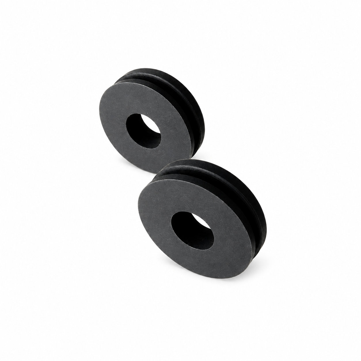
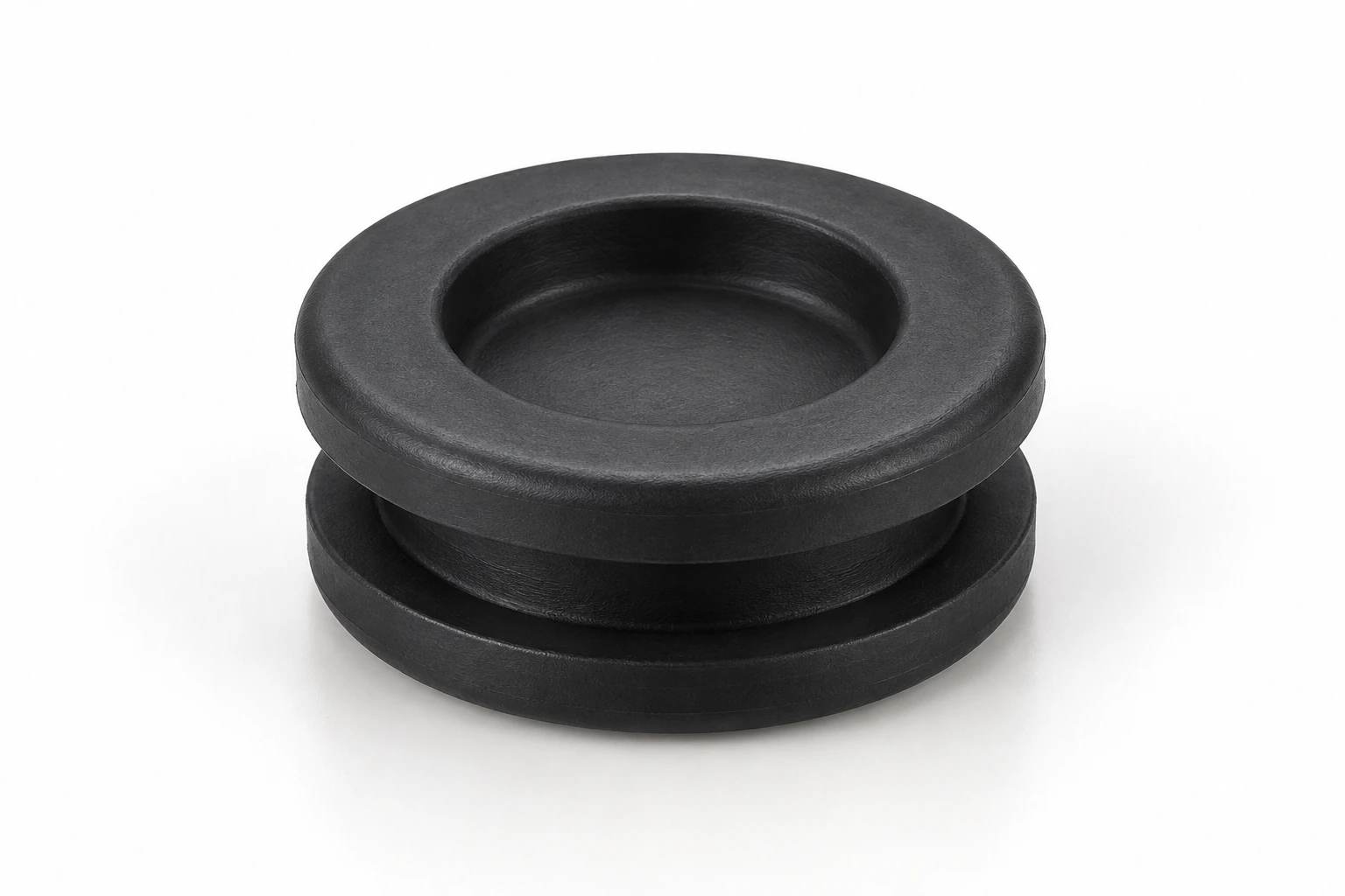
Custom manufacturing example · Hot-selling waterproof rubber cable grommet/rubber flat grommet
CUSTOM RUBBER & SILICONE MANUFACTURING
A custom component for your assembly.
Define the mating surfaces, dimensions and working conditions. ETOL manufactures the part to the agreed design and material.
Share the part, its application and your estimated quantity.

Selected for the contact, temperature and movement
Define the visible surfaces and intended color
Develop holes, lips and walls around the mating parts
Match the attachment and installation method
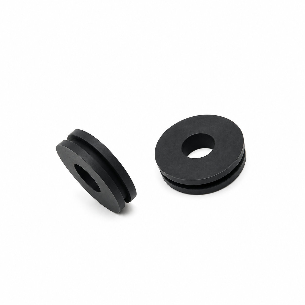
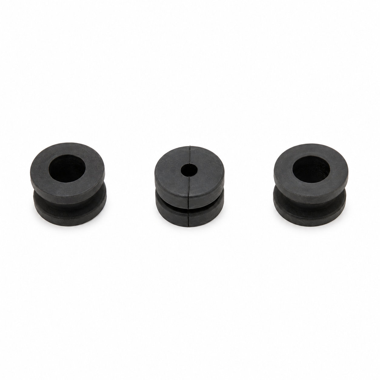
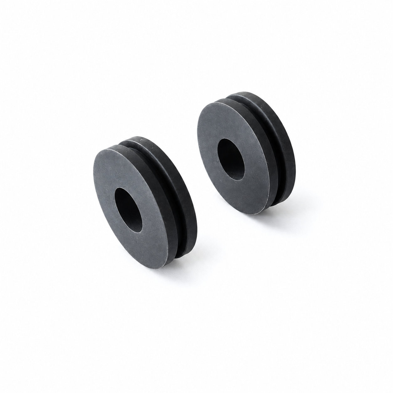
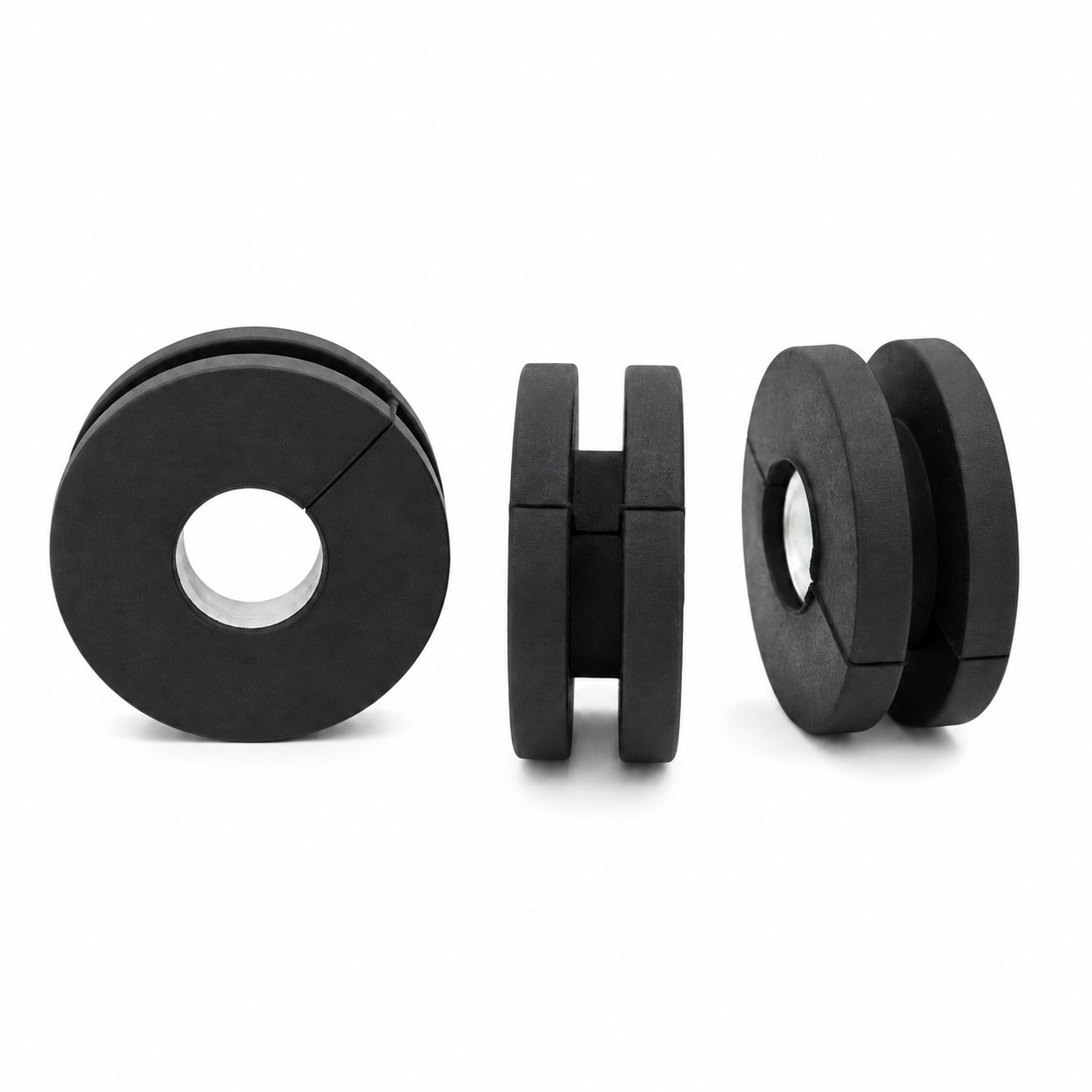
A rubber flat grommet should rest naturally against its mating panel while providing the intended passage around the cable. For a waterproof-oriented arrangement, the flat appearance should correspond with consistent contact beneath the flange rather than only an even-looking outer face.
ETOL can customize the material, dimensions, color and identification details. Include surface finish and nearby features in the mounting assessment. A local ridge under the flange may lift another area even when the grommet fits the nominal hole size.
Seat the rubber without twisting and route the cable so it does not pull the flat section into a dish shape. Evaluate required moisture exclusion with the final cable position and surrounding assembly. During servicing, clear particles from the contact area before reseating a displaced entry. If the flange no longer lies correctly, inspect the retained profile and cable approach instead of pressing it down beneath an adjoining cover. Replace damaged rubber and correct the cause of repeated distortion before the entry is concealed again.
Photos illustrate structure or material only. A local ridge under the flange may lift another area even when the grommet fits the nominal hole size. ETOL directly manufactures custom-shaped silicone and rubber parts to your requirements.
FIND THE RIGHT FIT
Choose a profile to compare part numbers and dimensions. Inch and metric sizes are listed in separate tables.
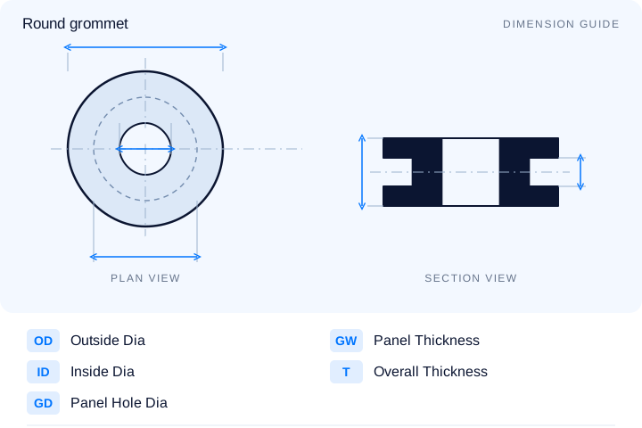
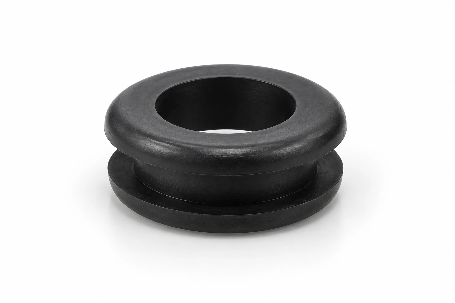
274 entries for Type D round through-hole grommets. Original fractions are retained, and exactly equivalent standard inch fractions replace decimal values where possible. Other values remain decimal inches.
| P/N | ID (C) | GD (A) | OD (D) | GW (B) | T (E) | Unit |
|---|---|---|---|---|---|---|
| RG2001 | 7/64 | 5/32 | 1/4 | 3/32 | 11/64 | inch |
| RG2002 | 7/64 | 5/32 | 1/4 | 3/64 | 11/64 | inch |
| RG2003 | 5/32 | 7/32 | 9/32 | 3/32 | 7/32 | inch |
| RG2004 | 1/8 | 3/16 | 5/16 | 1/16 | 3/16 | inch |
| RG2005 | 9/64 | 1/4 | 5/16 | 5/64 | 1/4 | inch |
| RG2006 | 5/32 | 1/4 | 5/16 | 7/64 | 13/64 | inch |
| RG2007 | 1/8 | 3/16 | 11/32 | 1/16 | 7/32 | inch |
| RG2008 | 1/8 | 1/4 | 11/32 | 1/16 | 7/32 | inch |
| RG2009 | 1/8 | 1/4 | 11/32 | 3/32 | 1/4 | inch |
| RG2010 | 9/64 | 3/16 | 11/32 | 1/16 | 3/16 | inch |
| RG2011 | 3/16 | 9/32 | 13/32 | 3/32 | 5/16 | inch |
| RG2012 | 3/16 | 5/16 | 13/32 | 1/16 | 7/32 | inch |
| RG2013 | 3/16 | 9/32 | 7/16 | 3/32 | 7/32 | inch |
| RG2014 | 3/16 | 5/16 | 7/16 | 1/16 | 3/16 | inch |
| RG2015 | 3/16 | 5/16 | 7/16 | 1/4 | 3/8 | inch |
866 entries for round panel openings. Compare the outside diameter, inside diameter, panel hole, panel thickness and overall thickness for the required fit.
| P/N | OD | ID | GD | GW | T | Unit |
|---|---|---|---|---|---|---|
| RG6-2-4-1 | 6 | 2 | 4 | 1 | 3 | mm |
| RG6-2-4-1.5 | 6 | 2 | 4 | 1.5 | 3.5 | mm |
| RG6-2-4-2 | 6 | 2 | 4 | 2 | 4 | mm |
| RG8-2-6-1 | 8 | 2 | 6 | 1 | 3.4 | mm |
| RG8-2-6-1.5 | 8 | 2 | 6 | 1.5 | 3.9 | mm |
| RG8-2-6-2 | 8 | 2 | 6 | 2 | 4.4 | mm |
| RG8-3-6-1 | 8 | 3 | 6 | 1 | 3.4 | mm |
| RG8-3-6-1.5 | 8 | 3 | 6 | 1.5 | 3.9 | mm |
| RG8-3-6-2 | 8 | 3 | 6 | 2 | 4.4 | mm |
| RG8-4-6-1 | 8 | 4 | 6 | 1 | 3.4 | mm |
| RG8-4-6-1.5 | 8 | 4 | 6 | 1.5 | 3.9 | mm |
| RG8-4-6-2 | 8 | 4 | 6 | 2 | 4.4 | mm |
| RG10-3-7-1 | 10 | 3 | 7 | 1 | 4 | mm |
| RG10-3-7-1.5 | 10 | 3 | 7 | 1.5 | 4.5 | mm |
| RG10-3-7-2 | 10 | 3 | 7 | 2 | 5 | mm |
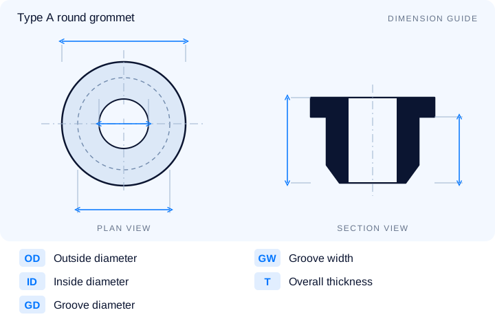
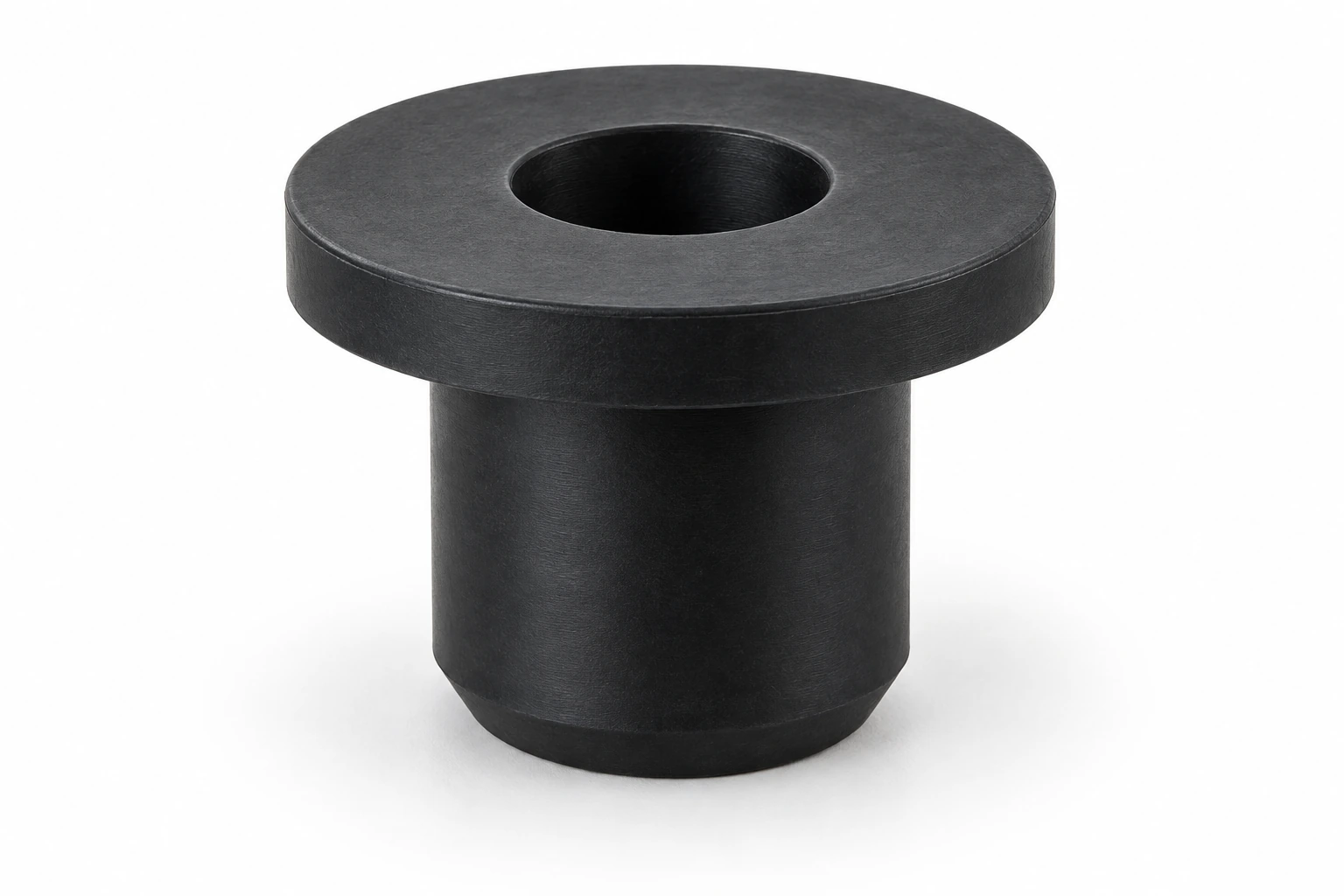
98 GRA sizes with a flanged sleeve profile. Compare the inside diameter, groove diameter and sleeve dimensions.
| P/N | ID | OD | GD | GW | T | Unit |
|---|---|---|---|---|---|---|
| GRA5000 | 2 | 8 | 5 | 7 | 8.5 | mm |
| GRA5001 | 3 | 8 | 5 | 7 | 8.5 | mm |
| GRA5002 | 3.5 | 9 | 6 | 8 | 9.5 | mm |
| GRA5003 | 3.2 | 8.2 | 6 | 8 | 9 | mm |
| GRA5004 | 3.5 | 11 | 6.8 | 8 | 10 | mm |
| GRA5005 | 4 | 10 | 7 | 8 | 9.5 | mm |
| GRA5006 | 4 | 11.5 | 7.3 | 8 | 10 | mm |
| GRA5007 | 4.5 | 12 | 7.8 | 8 | 10 | mm |
| GRA5008 | 4.5 | 11 | 8 | 8 | 9.5 | mm |
| GRA5009 | 5.5 | 13 | 9 | 8 | 10 | mm |
| GRA5010 | 5 | 12.5 | 8.3 | 8 | 10 | mm |
| GRA5011 | 5 | 13 | 9 | 9 | 11 | mm |
| GRA5012 | 6 | 14 | 10 | 9 | 11 | mm |
| GRA5013 | 7 | 15 | 11 | 10 | 12 | mm |
| GRA5014 | 7.5 | 16 | 12 | 10 | 12 | mm |
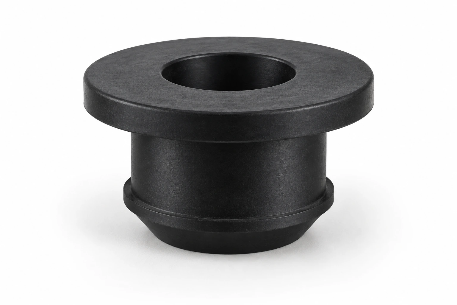
47 RGB sizes with a retaining lip below the mounting groove. Check the groove width and overall thickness for the panel assembly.
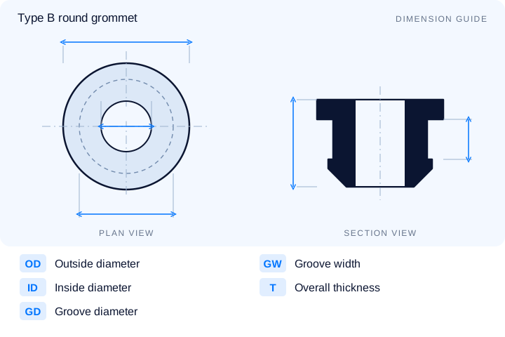
| P/N | ID | OD | GD | GW | T | Unit |
|---|---|---|---|---|---|---|
| RGB6001 | 2 | 8.5 | 4.6 | 3 | 8 | mm |
| RGB6002 | 2.5 | 9 | 5 | 3 | 7 | mm |
| RGB6003 | 3 | 9.5 | 5.5 | 3 | 7 | mm |
| RGB6004 | 3.5 | 10 | 6 | 4 | 8 | mm |
| RGB6005 | 4 | 10.5 | 6.5 | 4 | 8 | mm |
| RGB6006 | 4.5 | 11 | 7 | 4 | 8 | mm |
| RGB6007 | 5 | 11.5 | 7.5 | 4 | 8 | mm |
| RGB6008 | 5.5 | 12 | 8 | 4 | 8 | mm |
| RGB6009 | 6 | 12.5 | 8.5 | 4 | 8 | mm |
| RGB6010 | 6.2 | 13 | 9 | 5 | 9 | mm |
| RGB6011 | 6.5 | 13.5 | 9.5 | 5 | 9 | mm |
| RGB6012 | 7 | 14 | 10 | 5 | 9 | mm |
| RGB6013 | 7.5 | 14.5 | 10.5 | 5 | 9 | mm |
| RGB6014 | 8 | 15 | 11 | 5 | 9 | mm |
| RGB6015 | 8.5 | 15.5 | 11.5 | 5 | 9 | mm |
39 BGA sizes with a closed central membrane. Match dimensions A through E to the section drawing and the panel opening.
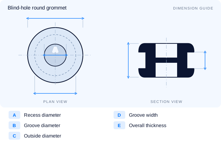
| P/N | A | B | C | D | E | Unit |
|---|---|---|---|---|---|---|
| BGA1001 | 10 | 12 | 17 | 2.5 | 7.5 | mm |
| BGA1002 | 14 | 16 | 21 | 2.5 | 9.5 | mm |
| BGA1003 | 15 | 20 | 26 | 2 | 9 | mm |
| BGA1004 | 18 | 22 | 28 | 2.5 | 9.5 | mm |
| BGA1005 | 20 | 25 | 33 | 2.5 | 11 | mm |
| BGA1006 | 22 | 27 | 34 | 1.6 | 9 | mm |
| BGA1007 | 22 | 28 | 34 | 2.5 | 10 | mm |
| BGA1008 | 25 | 30 | 40 | 3 | 10 | mm |
| BGA1009 | 24 | 32 | 40 | 2.5 | 11 | mm |
| BGA1010 | 30 | 35 | 45 | 2.5 | 10 | mm |
| BGA1011 | 30 | 38 | 45 | 3 | 12 | mm |
| BGA1012 | 32 | 40 | 47 | 3 | 10.5 | mm |
| BGA1013 | 35 | 42 | 50 | 2.5 | 10.5 | mm |
| BGA1014 | 36 | 47 | 53 | 3 | 10 | mm |
| BGA1015 | 42 | 48 | 58 | 6 | 16 | mm |
Can't find the right size? Contact us for custom dimensions tailored to your requirements.
Identify key dimensions, mating surfaces and quantity
Agree the compound and manufacturing approach
Review the fit and agreed requirements in the assembly
Manufacture and check against the approved requirements
Identify temperature, contact fluids and repeated movement.
Consider hardness together with wall thickness and support.
Check access, mating dimensions and the fitting sequence.
Yes. Show the receiving opening, contact surfaces and clearance limits. We can review the dimensions and retaining features around the intended fit.
Agree the critical dimensions, material, hardness, visible surfaces and sample requirements. Explain how the part is installed and which interfaces control its function.
A sample can help explain the structure. Compare it with the assembly because wear, swelling or compression may have changed its original dimensions.
The material, part geometry, tooling, quantity and finishing affect the quotation. Include the intended batch size and delivery destination when describing your requirements.
DISCUSS THIS COMPONENT
Share the fit, operating conditions and quantity with our manufacturing team.
EXPLORE RELATED DESIGNS
Explore similar part structures and applications for your next project.