Working conditions
Identify temperature, contact fluids and repeated movement.

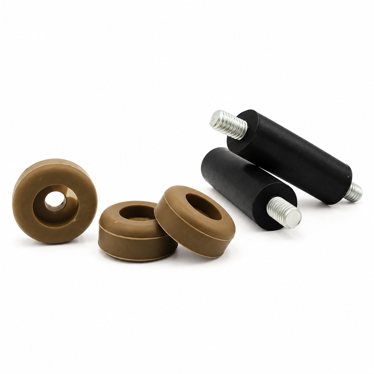
Custom manufacturing example · Round tips foot leg protect rubber feet for chair legs
CUSTOM RUBBER & SILICONE MANUFACTURING
A custom component for your assembly.
Define the mating surfaces, dimensions and working conditions. ETOL manufactures the part to the agreed design and material.
Share the part, its application and your estimated quantity.

Selected for the contact, temperature and movement
Define the visible surfaces and intended color
Develop holes, lips and walls around the mating parts
Match the attachment and installation method
A chair can rock even when all of its replacement feet have the same outside height. Rubber feet for chair legs need to reach their intended internal seats, and one leg may stop early if its end shape or receiving cavity differs. Seating depth should be checked before changing the base thickness.
For a round tip, compare the leg diameter across the portion that enters the cover. Taper, a weld or a damaged edge can prevent full insertion. The base profile should also suit the angle at which the chair leg meets the floor during normal use.
Fit the feet onto clean, smooth ends and assess the chair as a complete assembly. Avoid trimming the rubber to conceal a receiving mismatch. During maintenance, inspect for a rolled rim or a base thinning on one side. A correctly matched replacement should preserve both retention around the leg and the intended floor contact, keeping hard edges covered as the chair is repositioned.
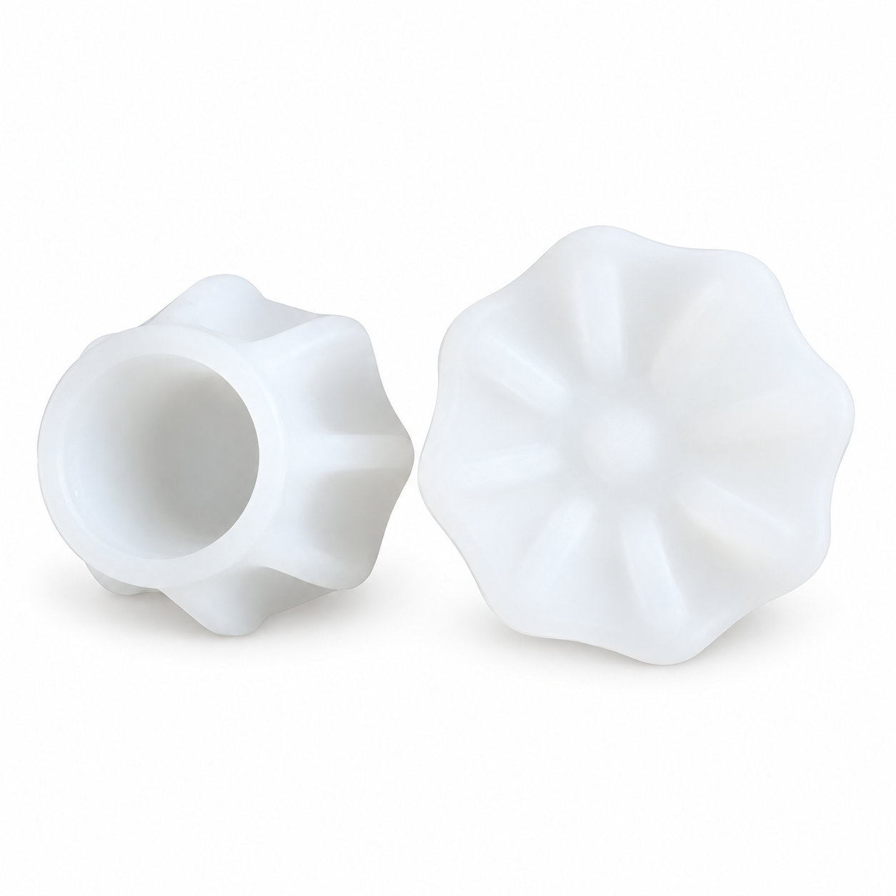
Photos illustrate structure or material only. The base profile should also suit the angle at which the chair leg meets the floor during normal use. ETOL directly manufactures custom-shaped silicone and rubber parts to your requirements.
FIND THE RIGHT FIT
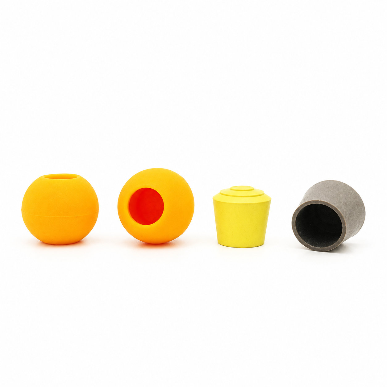
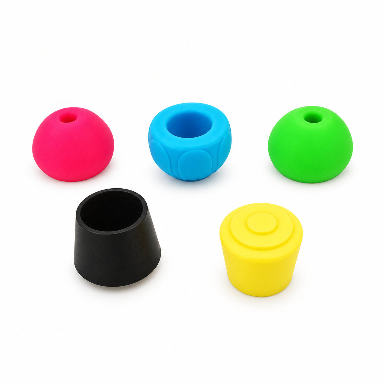
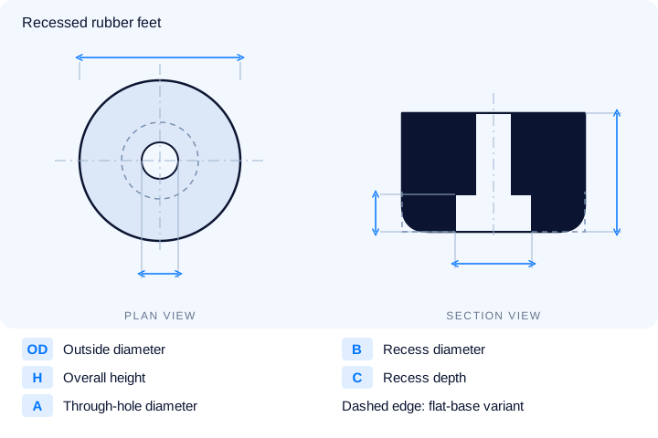
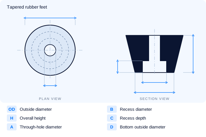
Choose hemispherical, tapered or recessed rubber feet and compare the mounting dimensions. All values are in millimeters. Use the drawing labels for each product; a dash marks a dimension not supplied in the source.
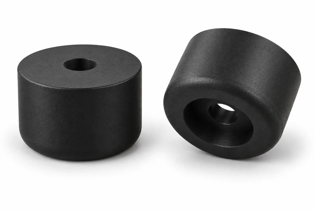
12 sizes for recessed rubber feet, including flat and rounded bases. The Base column identifies the lower-edge style. C is recess depth; the appearance rendering shows a rounded-base example.
| P/N | OD | H | A | B | C | Base | Unit |
|---|---|---|---|---|---|---|---|
| RBB7810 | 19 | 7.2 | 4.8 | 9.6 | 3.2 | Flat | mm |
| RBB7809 | 19 | 9.5 | 3.17 | 9.5 | 4 | Flat | mm |
| RBB7811 | 24 | 11 | 6 | 12 | 6 | Flat | mm |
| RBB7812 | 26.5 | 13 | 4.7 | 9.5 | 5 | Flat | mm |
| RBB7813 | 37 | 15 | 6 | 12 | 8 | Flat | mm |
| RBB7818 | 12.7 | 6.35 | 3.1 | 6.35 | 4 | Rounded | mm |
| RBB7817 | 26.5 | 21 | 4.7 | 9.5 | 11 | Rounded | mm |
| RBB7819 | 38 | 38 | 6 | 19 | 9.5 | Rounded | mm |
| RBB7820 | 38 | 38 | 6.5 | 19.5 | 9.5 | Rounded | mm |
| RBB7821 | 41 | 18 | 8.3 | 9.5 | 6 | Rounded | mm |
| RBB2101 | 12.7 | 9.53 | 3.97 | 7.94 | 4 | Rounded | mm |
| RBB2102 | 15 | 4 | 3 | 6 | 2 | Rounded | mm |
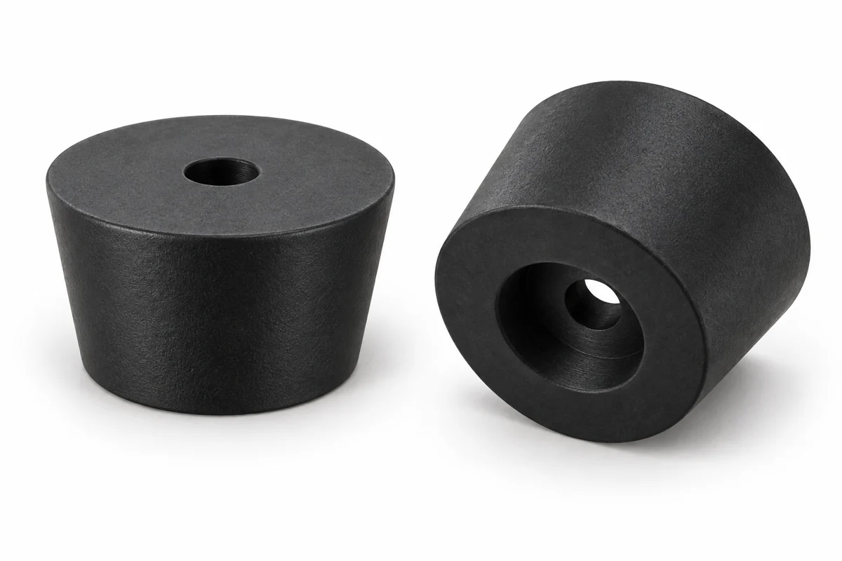
83 sizes for tapered rubber feet. C is recess depth and D is bottom outside diameter. A dash means that dimension was not supplied; match all available dimensions before selecting a size.
| P/N | OD | H | A | B | C | D | Unit |
|---|---|---|---|---|---|---|---|
| RBA7801 | 12 | 7 | 3 | 6 | 5.4 | — | mm |
| RBA7826 | 15.88 | 12.7 | 3.97 | 7.94 | 6.35 | — | mm |
| RBA7827 | 19.05 | 14.29 | 4.76 | 9.53 | 6.35 | — | mm |
| RBA7828 | 22.23 | 12.7 | 4.76 | 9.53 | 10.32 | — | mm |
| RBA7829 | 23.81 | 15.88 | 5.56 | 11.11 | 11.11 | — | mm |
| RBA7802 | 24 | 16 | 6 | 12 | 8 | — | mm |
| RBA7803 | 25 | 15 | 4 | 6 | 6 | — | mm |
| RBA7830 | 26.99 | 21.43 | 4.76 | 9.53 | 11.11 | — | mm |
| RBA7805 | 34 | 19 | 4.5 | 9 | 9 | — | mm |
| RBA7808 | 38 | 22.5 | 5 | 12 | 13 | — | mm |
| RBA7806 | 38 | 24 | 5 | 12 | 13 | — | mm |
| RBA7807 | 38 | 30 | 5.5 | 12 | 19 | — | mm |
| RBA1001 | 10.5 | 4 | 3 | 6 | — | 9 | mm |
| RBA1002 | 11 | 6 | 3 | 6 | — | 9 | mm |
| RBA1005 | 12 | 9 | 3 | 6 | — | 8 | mm |
5 sizes with a curved outer profile and recessed mounting hole. C is the recess depth.
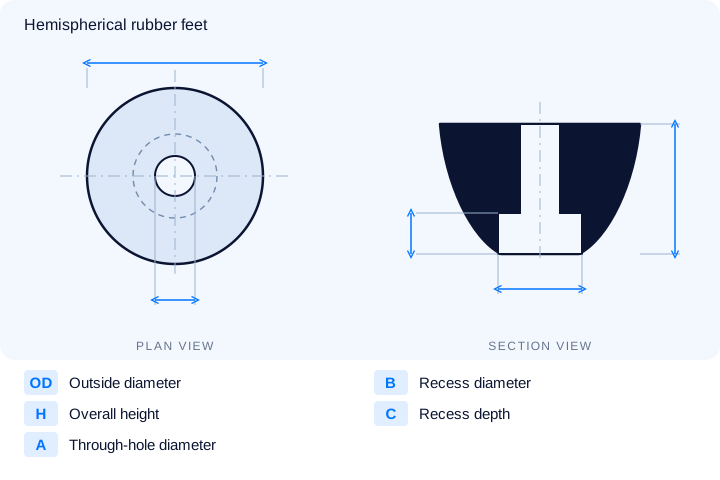
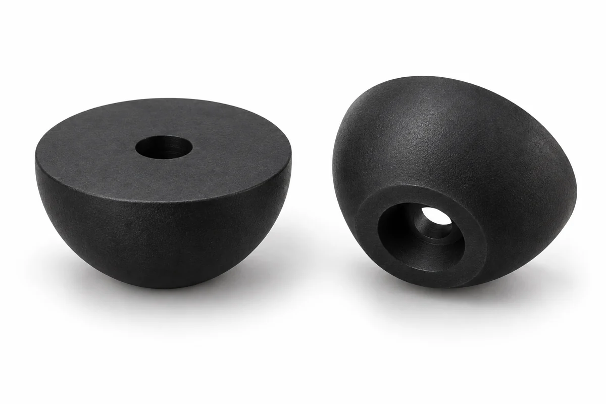
| P/N | OD | H | A | B | C | Unit |
|---|---|---|---|---|---|---|
| RBD7822 | 15 | 4.5 | 3.75 | 6.7 | 2 | mm |
| RBD7823 | 23.7 | 10 | 4 | 7 | 7 | mm |
| RBD7825 | 30 | 12 | 8 | 10 | 6 | mm |
| RBD7824 | 30 | 16 | 8 | 10 | 10 | mm |
| RBD4105 | 41 | 18 | 8.3 | 9.5 | 6 | mm |
Can't find the right size? Contact us for custom dimensions tailored to your requirements.
Identify key dimensions, mating surfaces and quantity
Agree the compound and manufacturing approach
Review the fit and agreed requirements in the assembly
Manufacture and check against the approved requirements
Identify temperature, contact fluids and repeated movement.
Consider hardness together with wall thickness and support.
Check access, mating dimensions and the fitting sequence.
Yes. Show the receiving opening, contact surfaces and clearance limits. We can review the dimensions and retaining features around the intended fit.
Agree the critical dimensions, material, hardness, visible surfaces and sample requirements. Explain how the part is installed and which interfaces control its function.
A sample can help explain the structure. Compare it with the assembly because wear, swelling or compression may have changed its original dimensions.
The material, part geometry, tooling, quantity and finishing affect the quotation. Include the intended batch size and delivery destination when describing your requirements.
DISCUSS THIS COMPONENT
Share the fit, operating conditions and quantity with our manufacturing team.
EXPLORE RELATED DESIGNS
Explore similar part structures and applications for your next project.